عضویت
عضویت  ورود اعضا
 راهنمای خرید


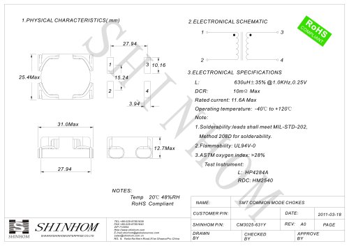
Isolated 3W Wide Input Dual Output DC/DC Converters0 pages

NDTD SERIES
Isolated 3W Wide Input Dual Output DC/DC Converters
SELECTION GUIDE
Order code
Input
voltage
Output current
Rated output
voltage
MIN. Load 1 Full load
V (NOM.)
FEATURES
nt compliant
RoHS
nt
Industry standard footprint
nt
Power density 0.90W/cm3
nt wide input range
2:1
nt isolated output
Dual
nt circuit protection
Short
nt profile 24 pin case
Low
nt
Operating temperature range -40ºC to 85ºC
nt and line regulation <1% on both
Load
outputs
nt heatsink required
No
NDTD0503C
NDTD0505C
NDTD0512C
NDTD0515C
NDTD1203C
NDTD1205C
NDTD1212C
NDTD1215C
NDTD2403C
NDTD2405C
NDTD2412C
NDTD2415C
NDTD4803C
NDTD4805C
NDTD4812C
NDTD4815C
V
mA
mA
5
5
5
5
12
12
12
12
24
24
24
24
48
48
48
48
±3.3
±5
±12
±15
±3.3
±5
±12
±15
±3.3
±5
±12
±15
±3.3
±5
±12
±15
±113
±75
±31
±25
±113
±75
±31
±25
±113
±75
±31
±25
±113
±75
±31
±25
±454
±300
±125
±100
±454
±300
±125
±100
±454
±300
±125
±100
±454
±300
±125
±100
nt 12V, 24V & 48V Input
5V,
nt 5V, 12V & 15V Output
3.3V,
nt
Internal SMD construction
nt encapsulated
Fully
DESCRIPTION
The NDTD series is a range of low profile DC/DC
converters offering dual outputs over a 2:1 input
voltage range. All parts deliver 3W output power
up to 85ºC without heatsinking. A flyback oscillator design with isolated feedback is used to give
regulation over the full operating range of 25% to
100% of full load. It is strongly recommended that
external capacitors be used on input and output
to guarantee performance over full load and input
voltage range (see application notes for guidance).
The plastic case is rated to UL94V-0 and encapsulant to UL94V-1 and the connection pins are
formed from a tin plated alloy 42 leadframe.
www.shinhom.com
890
804
764
773
343
321
311
310
170
156
148
146
86
79
76
75
67
72
76
75
73
75
78
78
73
78
82
82
72
76
80
81
30
31
36
34
30
29
32
36
30
30
35
41
30
30
35
36
1671
1675
2075
2080
1667
1669
2090
2045
INPUT CHARACTERISTICS
Parameter
Voltage range
nt
Footprint 4.73cm2
nt
1kVDC isolation
Input
Efficiency 2 Isolation
MTTF 3
current
(MIN.) capacitance
full load
mA
%
pF
kHrs
Reflected ripple current 4
Conditions
MIN.
TYP.
MAX.
5V input types
12V input types
24V input types
48V input types
5V input types
12V, 24V & 48V input types
4.5
9
18
36
5
12
24
48
40
30
9
18
36
75
90
40
Units
VDC
mA p-p
ABSOLUTE MAXIMUM RATINGS
Short-circuit protectiont
Lead temperature 1.5mm from case for 10 secondst
Minimum output load for specification1
Input voltage 5V types
Input voltage 12V types
Input voltage 24V types
Input voltage 48V types
Free air space
Continuous
300°C
25% of rated output
10V
20V
40V
80V
10mm MIN. around component
1.tPlease refer to output load application note section on page 3.
2. Measured at full load with external input/output capacitors, refer to test circuit.
3. Calculated using MIL-HDBK-217F with nominal input voltage at full load (ground benign) at 25°C.
4. Please refer to reflected ripple current measurement circuit on page 3.
t All specifications typical at TA=25°C, nominal input voltage and rated output current unless otherwise specified.
Page of 4
"