عضویت
عضویت  ورود اعضا
 راهنمای خرید


Frequency- and voltage monitoring0 pages

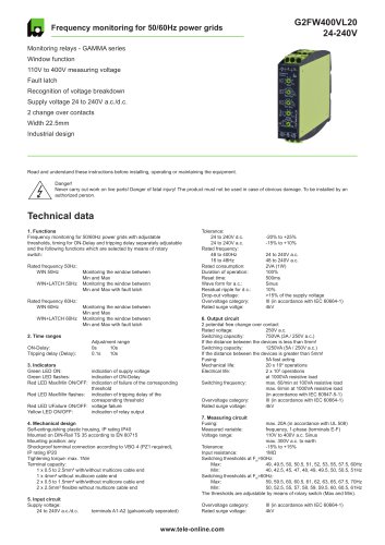
Frequency- and voltage monitoring
G2FW50HzYFA02
Monitoring relays - GAMMA series
in 3-phase mains in accordance with VDE 0126-1-1
Quick net error recognition
Connection of neutral wire necessary
Supply voltage selectable via power modules or switching power supply
2 change over contacts
Width 22.5mm
Industrial design
A1 I N I «
L1 I L2 I u
Technical data
1. Functions
Frequency monitoring in Phase L1 in accordance with VDE 0126-1-1 with
fixed ON-Delay and fixed thresholds.
WINF (Frequency) Monitoring the window between Min and Max
Voltage monitoring in 3-phase mains in accordance with VDE 0126-1-1
with fixed ON-Delay, fixed thresholds and adjustable 10-minutes-
average.
WINV (Voltage)
2. Time ranges
ON-Delay:
OFF-Delay:
U< 80% of UN
U > 115% of UN
f<47.5
f > 50.2
Monitoring the window between Min and Max
Adjustment range
fixed, 30s
< 200ms
< 200ms
< 200ms
< 200ms
3. Indicators
3.1 Indicators for voltage monitoring
Red LED U.
ON:
One of the 3-phases (L-N) has exceeded the
10-minutes-average
Red LED U„ flashes: One of the 3-phases current values (L-N)
Average r v '
has exceeded the adjustable threshold
Red LED UFai|ure ON: One of the 3-phases (L-N) is beyond the
fixed voltage thresholds
3.2 Indicators for frequency monitoring
Red LED>fON: indication of failure for maximum threshold
Red LED <f ON: indication of failure for minimum threshold
Red LED >f and <f ON: invalid measurement voltage to phase L1
3.3 Indicators for relay outputs
Yellow LED ON/OFF: indication of relay output
Yellow LED flashes: indication of ON-Delay
4. Mechanical design
Self-extinguishing plastic housing, IP rating IP40
Mounted on DIN rail TS 35 according to EN 60715
Mounting position: any
Shockproof terminal connection according to VBG 4 (PZ1 required),
IP rating IP20
Tightening torque: max. 1Nm
Terminals capacity:
1 x 0.5 to 2.5mm2 with/without multicore cable end
1 x 4mm2 without multicore cable end
2 x 0.5 to 1.5mm2 with/without multicore cable end
2 x 2.5mm2 flexible without multicore cable end
5. Input circuit
Supply voltage:
12V to 400V a.c.
Tolerance:
Rated frequency:
terminals A1-A2 (galvanically separated)
selectable via power module type TR2
according to specification of power module
according to specification of power module
Supply voltage:
24V d.c.
Tolerance:
Rated frequency:
Rated consumption:
Duty cycle:
Reset time:
Residual ripple of DC:
Drop-out voltage:
Overvoltage category:
Rated surge voltage:
6. Output circuit
2 potential free change
Rated voltage:
Switching capacity:
If the distance between
Switching capacity:
If the distance between
Fusing:
Mechanical life:
Electrical life:
Switching frequency:
Overvoltage category:
Rated surge voltage:
7. Measuring circuit
Fusing:
Frequency monitoring
Measured variable:
Measurement input:
50 Hz
Switching threshold:
Max:
Min:
Voltage monitoring
Measured variable:
Measurement input:
230V a.c.
Overload capacity:
230V a.c.
Input resistance:
3N~ 400/230V
Switching threshold Us
Max:
Min:
10-minutes-average:
Overvoltage category:
Rated surge voltage:
terminals A1-A2 (galvanically separated)
selectable via switching power supply
type SNT2
according to specification of switching
power supply
according to specification of switching
power supply
2VA (1.5W)
100%
85ms
>30% of supply voltage
III (in accordance with IEC 60664-1)
4kV
over contacts
250V AC
750VA(3A/250V a.c.)
the devices is less than 5mm!
1250VA(5A/ 250V a.c.)
the devices is greater than 5mm!
5Afast acting
20 x 106 operations
2 x 10⁵ operations
at 1000VA resistive load
max. 60/min at 100VA resistive load
max. 6/min at 1000VA resistive load
(in accordance with IEC 60947-5-1)
III (in accordance with IEC 60664-1)
4kV
max. 20A(in accordance with UL508)
frequency of phase L1
terminal N-L1
50.2Hz
47.5Hz
a.c. Sinus
terminals N-L1, N-L2, N-L3
440V a.c.
1MQ
115% of UN (264.5V)
80% of UN (184V)
+10% to+15% of UN
III (in accordance with IEC 60664-1)
4kV
www.tele-online.com
"