عضویت
عضویت  ورود اعضا
 راهنمای خرید


Frequency monitoring for 50/60Hz power grids0 pages
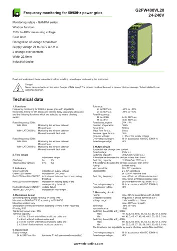
Frequency monitoring for 50/60Hz power grids
G2FW400VL20
24-240V
Monitoring relays - GAMMA series
Window function
110V to 400V measuring voltage
Fault latch
Recognition of voltage breakdown
Supply voltage 24 to 240V a.c./d.c.
2 change over contacts
Width 22.5mm
Industrial design
Read and understand these instructions before installing, operating or maintaining the equipment.
t
t
t
Danger!
Never carry out work on live parts! Danger of fatal injury! The product must not be used in case of obvious damage. To be installed by an tt
authorized person.
Technical data
1. Functions
Frequency monitoring for 50/60Hz power grids with adjustable
thresholds, timing for ON-Delay and tripping delay separately adjustable
and the following functions which are selected by means of rotary
switch:
Rated frequency 50Hz:
t
WIN 50Hzttt
tttttt
t
WIN+LATCH 50Hzt
tttttt
Monitoring the window between
Min and Max
Monitoring the window betwenn
Min and Max with fault latch
Rated frequency 60Hz:
t
WIN 60Hzttt
tttttt
t
WIN+LATCH 60Hzt
tttttt
Monitoring the window between
Min and Max
Monitoring the window between
Min and Max with fault latch
2. Time ranges
ttttttt
ON-Delay:ttttt
Tripping delay (Delay):tt
Adjustment range
0stt
10s
0.1st
10s
3. Indicators
Green LED ON:tttt
Green LED flashes:ttt
Red LED Max/Min ON/OFF:t
ttttttt
Red LED Max/Min flashes:t
ttttttt
Red LED UFailure ON/OFF:t
Yellow LED ON/OFF:ttt
indication of supply voltage
indication of ON-Delay
indication of failure of the corresponding t
threshold
indication of tripping delay of the tt
corresponding threshold
voltage failure
indication of relay output
4. Mechanical design
Self-extinguishing plastic housing, IP rating IP40
Mounted on DIN-Rail TS 35 according to EN 60715
Mounting position: any
Shockproof terminal connection according to VBG 4 (PZ1 required),
IP rating IP20
Tightening torque: max. 1Nm
Terminal capacity:
t
1 x 0.5 to 2.5mm² with/without multicore cable end
t
1 x 4mm² without multicore cable end
t
2 x 0.5 to 1.5mm² with/without multicore cable end
t
2 x 2.5mm² flexible without multicore cable end
5. Input circuit
Supply voltage:
t
24 to 240V a.c./d.c.tt
terminals A1-A2 (galvanically seperated)
Tolerance:
t
24 to 240V d.c.ttt
t
24 to 240V a.c.ttt
Rated frequency:
t
48 to 400Hztttt
t
16 to 48Hztttt
Rated consumption:ttt
Duration of operation:tt
Reset time:ttttt
Wave form for a.c.:ttt
Residual ripple for d.c.:tt
Drop-out voltage:ttt
Overvoltage category:tt
Rated surge voltge:ttt
-20% to +25%
-15% to +10%
24 to 240V a.c.
48 to 240V a.c.
2VA (1W)
100%
500ms
Sinus
10%
>15% of the supply voltage
III (in accordance with IEC 60664-1)
4kV
6. Output circuit
2 potential free change over contact
Rated voltage:tttt
250V a.c.
Switching capacitiy:ttt
750VA (3A / 250V a.c.)
If the distance between the devices is less than 5mm!
Switching capacity:ttt
1250VA (5A / 250V a.c.)
If the distance between the devices is greater than 5mm!
Fusing:tttttt
5A fast acting
Mechanical life:tttt
20 x 106 operations
Electrical life:tttt
2 x 10⁵ operations
ttttttt
at 1000VA resistive load
Switching frequency:ttt
max. 60/min at 100VA resistive load
ttttttt
max. 6/min at 1000VA resisitve load
ttttttt
(in accordance with IEC 60947-5-1)
Overvoltage category:tt
III (in accordance with IEC 60664-1)
Rated surge voltage:ttt
4kV
7. Measuring circuit
Fusing:tttttt
max. 20A (in accordance with UL 508)
Measured variable:ttt
frequency, 1-phase (terminals E-F)
Voltage range:tttt
110V to 400V a.c. Sinus
ttttttt
max. 300V a.c. to earth
Tolerance:ttttt
-15% to +15%
Input resistance:tt
t
t
1MΩ
Switching thresholds at FN=50Hz:
t
Max:ttttt
49, 49.5, 50, 50.5, 51, 52, 53, 55, 57.5, 60Hz
t
Min:ttttt
40, 42.5, 45, 47, 48, 49, 49.5, 50, 50.5, 51Hz
Switching thresholds at FN=60Hz:
t
Max:ttttt
59, 59.5, 60, 60.5, 61, 62, 63, 65, 67.5, 70Hz
t
Min:ttttt
50, 52.5, 55, 57, 58, 59, 59.5, 60, 60.5, 61Hz
The thresholds are adjustable by means of rotary switch (Max and Min).
Overvoltage category:tt
Rated surge voltage:ttt
www.tele-online.com
III (in accordance with IEC 60664-1)
4kV