عضویت
عضویت  ورود اعضا
 راهنمای خرید


E6 Optical Kit Encoder0 pages
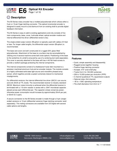
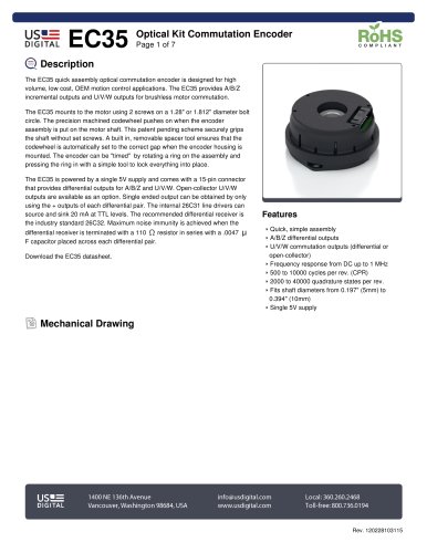
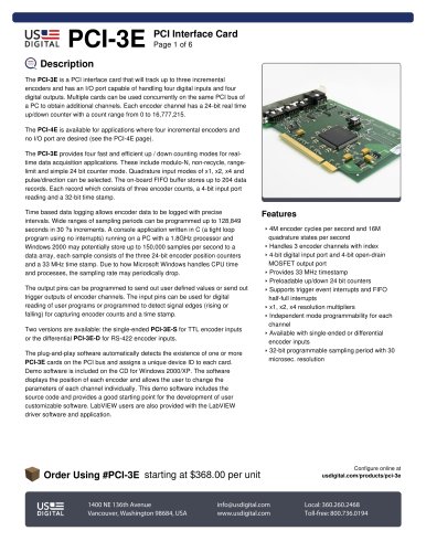
table.main {} tr.row {} td.cell {} div.block {} div.paragraph {} .font0 { font:6.00pt "Arial", sans-serif; } .font1 { font:7.00pt "Arial", sans-serif; } .font2 { font:8.00pt "Arial", sans-serif; } .font3 { font:10.00pt "Arial", sans-serif; } .font4 { font:13.00pt "Arial", sans-serif; } .font5 { font:18.00pt "Arial", sans-serif; } .font6 { font:24.00pt "Arial", sans-serif; } .font7 { font:33.00pt "Arial", sans-serif; } US= DIGITAL E6 Optical Kit Encoder Page 1 of 16 RoHS COMPLIANT Q Description The E6 Sϩries rotary encoder has a molded polycarbonate which utilizes either a 5-pin or 10-pin finger-latching connector. This optical incremental encoder is designed to easily mount to and dismount from an existing shaft to provide digital feedback information. The E6 Series is easy to add to existing applications and only consists of five main components; base, cover, hub/code wheel, optical encoder module and internal differential line driver (differential version only). The single-ended output version (S-option) is typically used with cables of 6 feet or less. For longer cable lengths, the differential output version (D-option) is recommended. The base and cover are both constructed of a rugged 20% glass filled polycarbonate. Attachment of the base to a surface may be accomplished by utilizing one of several machine screw bolt circle options. Positioning of the base to the centerline of a shaft is ensured by use of a centering tool (sold separately). The cover is securely attached to the base with two 4-40 flat head screws to provide a resilient package protecting the internal components. The internal components consist of a shatterproof mylar disk mounted to a precision machined aluminum hub and an encoder module. The module consists of a highly collimated solid state light source and monolithic phased array sensor, which together provide a system extremely tolerant to mechanical misalignments. For differential versions: the internal differential line driver (26C31) can source and sink 20mA at TTL levels. The recommended receiver is industry standard 26C32. Maximum noise immunity is achieved when the differential receiver is terminated with a 110-ohm resistor in series with a .0047 microfarad capacitor placed across each differential pair. The capacitor simply conserves power; otherwise power consumption would increase by approximately 20mA per pair, or 60mA for 3 pairs. A secure connection to the E6 Series encoder is made through a 5-pin (single-ended versions) or 10-pin (differential versions) finger-latching connector (sold separately). The mating connectors are available from US Digital with several cable options and lengths. Features Quick, simple assembly and disassembly Rugged screw-together housing Positive finger-latching connector Accepts .010" axial shaft play Tracks from 0 to 100,000 cycles/sec 256 to 10,000 puises per rvolution (PPR) 2 channel quadrature TTL squarewave outputs Optional index (3rd channel) -40 to +100C operating temperature Fits shaft diameters from 2mm to 1" I |P= 1400NE 136th Avenue info@usdigital.com Local:360.260.2468 DIGITAL Vancouver, Washington 98684, USA www.usdigital.com Toll-free: 800.736.0194 Rev. 111130165646
"