عضویت
عضویت  ورود اعضا
 راهنمای خرید


E7P OEM Optical Kit Encoder0 pages
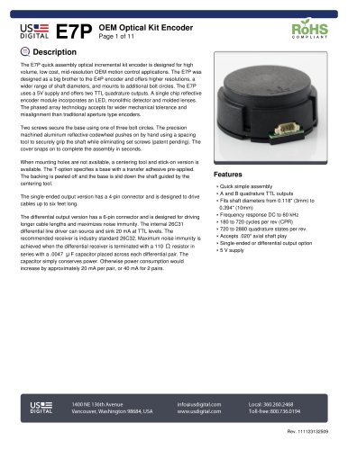
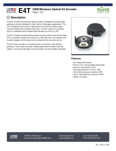
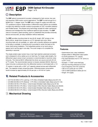
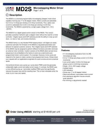
table.main {} tr.row {} td.cell {} div.block {} div.paragraph {} .font0 { font:6.00pt "Arial", sans-serif; } .font1 { font:7.00pt "Arial", sans-serif; } .font2 { font:8.00pt "Arial", sans-serif; } .font3 { font:10.00pt "Arial", sans-serif; } .font4 { font:11.00pt "Arial", sans-serif; } .font5 { font:13.00pt "Arial", sans-serif; } .font6 { font:18.00pt "Arial", sans-serif; } .font7 { font:23.00pt "Arial", sans-serif; } .font8 { font:33.00pt "Arial", sans-serif; } US= DIGITAL E7P OEM Optical Kit Encoder Page 1 of 11 RoHS COMPLIANT Q Description The E7P quick assembly optical incrϩmental kit encoder is designed for high volume, low cost, mid-resolution OEM motion control applications. The E7P was designed as a big brother to the E4P encoder and offers higher resolutions, a wider range of shaft diameters, and mounts to additional bolt circles. The E7P uses a 5V supply and offers two TTL quadrature outputs. A single chip reflective encoder module incorporates an LED, monolithic detector and molded lenses. The phased array technology accepts far wider mechanical tolerance and misalignment than traditional aperture type encoders. Two screws secure the base using one of three bolt circles. The precision machined aluminum reflective codewheel pushes on by hand using a spacing tool to securely grip the shaft while eliminating set screws (patent pending). The cover snaps on to complete the assembly in seconds. When mounting holes are not available, a centering tool and stick-on version is available. The T-option specifies a base with a transfer adhesive pre-applied. The backing is peeled off and the base is slid down the shaft guided by the centering tool. The single-ended output version has a 4-pin connector and is designed to drive cables up to six feet long. The differential output version has a 6-pin connector and is designed for driving longer cable lengths and maximizes noise immunity. The internal 26C31 differential line driver can source and sink 20 mA at TTL levels. The recommended receiver is industry standard 26C32. Maximum noise immunity is achieved when the differential receiver is terminated with a 110 Q resistor in sries with a .0047 |J F capacitor placed across each differential pair. The capacitor simply conserves power. Otherwise power consumption would increase by approximately 20 mA per pair, or 40 mA for 2 pairs. Features Quick simple assembly ^ A and B quadrature TTL outputs ^ Fits shaft diameters from 0.118" (3mm) to 0.394" (10mm) Frequency response DC to 60 kHz ► 180 to 720 cycles per rev (CPR) 720 to 2880 quadrature states per rev. ^ Accepts .020" axial shaft play Single-ended or differential output option 5 V supply I |P= 1400NE 136th Avenue info@usdigital.com Local:360.260.2468 DIGITAL Vancouver, Washington 98684, USA www.usdigital.com Toll-free: 800.736.0194 Rev. 111123132509
"