عضویت
عضویت  ورود اعضا
 راهنمای خرید


Reed Switches0 pages

The Comus Group of Companies
nnnn^^^^ The Comus Group of Companies
nnnn^^^^ The Comus Group of Companies
nnnnActuation of Reed Switches with a Permanent Magnet
nnnn(Examples of switching with the use of a moving magnet)
nnnnDirect Actuation:
nnnnRotation:
nnnnExamples of switching through rotational movement.
nnnnOTHER PRODUCTS
nnnnA magnet moved perpendicularly towards and
nnnnaway from a Reed Switch turns it off and
nnnnon once.
nnnnA magnet moved parallel to a Reed
nnnnSwitch operates it from one to three times.
nnnn, Closed
nnnnOpen
nnnnMagnet
nnnnA magnet swung towards and away
nnnnfrom a Reed Switch operates it once.
nnnnMagnet
nnnnA ring magnet moved parallel to a Reed closeli
nnnnSwitchs" axis operates it from one to three
nnnntimes.
nnnnIn General:
nnnnRing Magnet
nnnnFor all Reed Switches the standard pull-in sensitivity is given in the table.
nnnnOther pull-in sensitivities are available on request
nnnnContact Form A
nnnn=€1
nnnnContact Form B
nnnnMagnet Biasing Contact
nnnnContact Form B or C
nnnnNormally Closed Contact (Form B)
nnnnNormally Open Contact (Form C)
nnnnClosed
nnnnIndirect Actuation: Shielding
nnnnWith the stationary arrangement of a Reed Switch and magnet, the contact Reeds are dosed.
nnnnShould the magnetic field be diverted away from the Reed Switch by a shield of ferro
nnnnmagnetic material placed between the switch and the magnet, the contacts will open. When the
nnnnshield is removed, the contact Reeds become magnetically actuated and close.
nnnnOpen
nnnnMagnet
nnnn-<->- Closed
nnnn\
nnnnMagnetic shield
nnnnPull-in Sensitivity:
nnnnThe given pull-in sensitivity of the Reed Switch has a test equipment tolerance of ± 2 AT.
nnnnLife Expectancy:
nnnnThe life expectancy of a reed switch is dependent upon the load being switched. At
nnnnmaximum rated loads life expectancy is approximately I06 switching cycles. Lower load
nnnnratings can increase the life expectancy up to SxlO8 operations. The mechanical life
nnnnexpectancy can reach at least 10' operations. Through the switching of inductive, capacitive.
nnnnand lamp loads, the life expectancy is considerably reduced due to exceeding the specified
nnnnmaximum current.
nnnnAll dimensions are nominal, in millimeters unless otherwise stated. If further information is required, individual datasheets are available on our websites, and on CO.
nnnnAs part of the groups policy of continued product improvement, specifications may change without notice. Our sales office will be pleased to help you with the latest information on our products.
nnnnDil & Sil Reed Relay
nnnnReed relays consist of a switch and coil assembled into a housing, which
nnnncould be plastic metal or moulded.
nnnnCompared with electro-mechanical relays, reed relays are smaller in size
nnnnand generally have a faster response time, lower power consumption and
nnnnlonger life. Compared with solid state relays, reed relays have a real gal-
nnnnvanic isolation betweeen input and output The leakage current and the
nnnnON-resistance is much lower. Reed relays also can offer a higher dielectric
nnnnstrength.
nnnnReed Switch
nnnnReed Switches consist of two or three ferromagnetic blades (or reeds)
nnnnhermetically sealed inside a glass envelope. The construction ensures
nnnnprotection from the external environment. Three types ate available:
nnnnForm A (normally open), Form B (normally closed), and Form C
nnnn(changeover). Various voltage and current switching levels are available
nnnnand contact plating materials can be varied to acccommodate specific
nnnntypes of load.
nnnnMagnetic Proximity Switch
nnnnReed Proximity Switches are operated by a moving magnet and can be
nnnnused to detect many directions of movement When the magnet reach-
nnnnes the operate distance from the reed switch, the reed switch contacts
nnnnwill operate (open or close). Moving the magnet away will cause the
nnnnreed switch contacts to switch back to their original position.
nnnnTilt Switch
nnnnTilt switches are used to sense movement (tilt) of a device above and
nnnnbelow a horizontal axis. The angle through which the switch must move
nnnnfor proper operation (the differential angle) is measured from the point
nnnnof just make to just break; it is specified as a maximum. When selecting
nnnna tilt switch, it is important to ensure that the operating mechanism can
nnnnmove the switch through an angle greater than the differential angle.
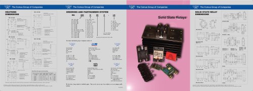
nnnnSolid State Relay
nnnnSolid State Relays (SSR) manufactured by the Comus Group of companies
nnnnare sold around the world. The sign, with no moving parts, means that
nnnnsolid state relays have an almost unlimited life expectancy compared with
nnnnelectromechanical relays. With no mechanical parts there is no contact
nnnnbounce, no sparks and no mechanical wear making solid state relays the
nnnnnatural choice in working environments where these features are impor-
nnnntant
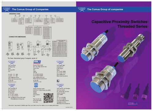
nnnnInductive & Capacitive Proximity
nnnnInductive Proximity sensors can measure ferrous metals. Capacitive Prox-
nnnnimity sensors can measure both metal and non-metalic objects, such as
nnnniron, water, oil, glass, plastic, etc The mounting distance will vary
nnnndepending on the material being sensed. Due to differing object conduc-
nnnntivity, permitivity, and water absorption. If the metal connects with
nnnnground (GND) then maximum sensing distance will be achieved.
nnnn9<
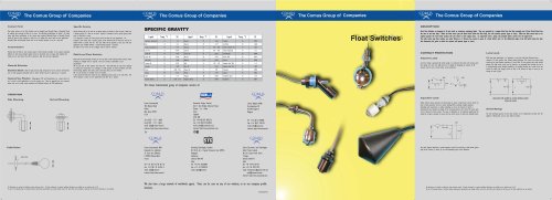
nnnnFloat Switch
nnnnReed Float Switches are designed to fit into tanks or containers contain-
nnnning liquid. They are operated by magnet fitted into the float assembly
nnnnand a Reed Switch fined into the stem of the float body. When the float
nnnnmoves past the Reed Switch inside the float body, the reed contacts op-
nnnnerate (open or close). When the float moves back to its original position
nnnnthe reed switch contacts will also return to their original state.
nnnnHybrid
nnnnA Hybrid sensor has multiple sensors and multiple processing techniques
nnnnto obtain and transmit more information than one could achieve from in-
nnnndependent sensors. Standard and custom packaging is available for pro-
nnnntection and ease of mounting. Hybrids consist of time proven sensors
nnnncombined with reaction time as little as 2ms.
nnnnHigh Voltage Reed Relay
nnnnReed relays consist of a switch and a coil fitted into a housing, which
nnnncould be plastic metal or moulded.
nnnnCompared with electromechanical relays, reed relays generally have a
nnnnfaster response rime, lower coil consumption, and are smaller in size.
nnnnFurthermore, the switch is sealed in a dry, inert atmosphere, prevent-
nnnning the ingress of contaminants.
nnnnFlow Switch
nnnnThe Flow Switch is designed to lit into a Tee connector within the pipe-
nnnnwork. The paddle section can be adjusted depending on the size of the
nnnnpipe. It operates as water flows through the pipe it pushes the paddle
nnnnup thus triggering the switch.
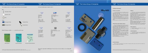
nnnnMagnet
nnnnMagents come in various sizes, materials, and coatings. Bare Magnets
nnnncan be supplied as a separate product or part of a proximity switch
nnnnset consisting of switch and magnet Cased Magnets can be supplied as
nnnna separate product, where you can select a magnet to suit your op-
nnnneration, or as part of a proximity switch set consisting of matching
nnnnswitch and magnet Materials available are Alnico/Alcomax, Ceramic
nnnnFerrite and Neodymium Iron Boron.
nnnnHigh Breakdown Switch
nnnnThe HBS line of reed switches is the Comus groups answer to the market
nnnndemands for a lower cost reed switch that is still capable of handling
nnnnhigh voltage applications. The HBS line of reed switches is ideal for cer-
nnnntain markets such as Medical applications; for example defibrillation
nnnnequipment where high reliability and excellent quality is absolutely es-
nnnnsential.
nnnnSTANDARD TEST COILS FOR
nnnnREED CONTACT UNITS
nnnnwinding
nnnnConfiguration of test colls
nnnnTest Coil Type | EN 119000 Test Coil nr. | Winding length 1 (mm) | Inside Coil Dia. 0 d (mm) | Outside Coil Dia. 0 e (mm) | Number of Turns | Nominal Cu-wire Diam. 0 (mm) | Nominal Resitance (Ohms) |
0211 | nr. 1 | 10 | 3.3 | ll | sooo | 0.063 | 600 |
0221 | nr. 7 | IS | 3.7 | II | sooo | 0.071 | 450 |
0229 | nr. 13 | 21 | 4.6 | ll | 5000 | 0.071 | 500 |
OSSI | nr. 2 | U | 4.6 | 13 | 5000 | 0.08 | 550 |
1035 | 13 | 4.8 | 14 | 10000 | 0.063 | 2000 | |
IS00 | nr. 21 | 48.2 | 7.3 | 14.2 | 10000 | 0.09 | 1000 |
1700 | nr. 12 | 20.S | 4.3 | 14 | 10000 | 0.08 | 1000 |
1800 | nr. 14 | 23 | S.5 | IS | 10000 | 0.08 | 1000 |
nr. 14 | 2S.4 | 7.6 | 12.1 | 10000 | 0.071 | 1500 | |
PSC | 2S.4 | 8.7S | 14 | 5000 | 0.1016 | 400 |
The Comus International group of companies consists of:
nnnnCOMUS
nnnnCOMUS
nnnnComus International
nnnn454 Allwood Road
nnnnClifton
nnnnNew Jersey 07012
nnnnU.S.A
nnnnTel: (1)973 - 777 - 6900
nnnnFax:(l)973 - 777 - 8405
nnnnemail: info@comus-intl.com
nnnnWebsite: http://www.comus-intl.com
nnnnISO 9001:2008
nnnnCERTIFICATE NO: 03-12314
nnnnCOMUS „™„
nnnn=(Ero=.
nnnnComus Technology BV
nnnnJan Campertstraat II
nnnn6416 SG Heerlen
nnnnThe Netherlands
nnnnTel: +31(0)45-54.39.345
nnnnFax: +31(0)45-54.27.216
nnnnemail: info@comus-intl.com
nnnnWebsite: http://www.dry-reeds.com
nnnnAssemtech Europe Limited
nnnnUnit 7, Rice Bridge Industrial Estate
nnnnThorpe - Le - Soken
nnnnEssex
nnnnEngland
nnnnCO 16 0HL
nnnnTel: +44 (0)1255 862236
nnnnFax: +44 (0)1255 862014
nnnnemail: sales@assemtech.co.uk
nnnnWebsite: http://www.assemtech.co.uk
nnnnISO 9001:2008
nnnnCERTIFICATE HO: FN 21080
nnnnSTG
nnnnSwitching Technologies Gunther
nnnnB-9, B-10, & C-l Special Economic Zone (MEPZ)
nnnnKadapperi
nnnnTambaram
nnnnChennai 600 045
nnnnIndia
nnnnComus Belgium BVBA
nnnnOverhaamlaan 40
nnnnB-3700 Tongeren
nnnnBelgium
nnnnTel: +32 (0)12 390400
nnnnFax: +32 (0)12 235754
nnnnemail: info@comus.be
nnnnWebsite: http://www.comus.be
nnnnCOMUS
nnnnComus Electronics and Technologies
nnnnIndia Private Limited
nnnnNo.3, Kamaraj Nagar 2nd Street
nnnnTambaram Sanatorium
nnnnChennai 600045
nnnnIndia
nnnnTel:+(9l)-(44)-432l9090
nnnnFax:+(9l)-(44)-22628l98
nnnnemail: info@comus-intl.com
nnnnWebsite: http://www.comusindia.com
nnnnWe also have a large network of worldwide agents. These can be seen on any of our websites, or on our company profile
nnnnbrochure.
nnnnCom/I/Hayl l/lss. I
nnnn:
nnnnC~^^ The Comus Group of Companies
nnnnComus Reed Switches
nnnn^2^^ The Comus Group of Companies
nnnnMUS
nnnnInternational
nnnnhSSifHtech
nnnnSwitching
nnnnTechnologies
nnnnGunther
nnnnca
nnnnTECHNOLOGY BV.
nnnnCOMUS
nnnnElectronics & Technologies
nnnnINDIA Private Limited
nnnnThe Comus Group of Companies
nnnnDESCRIPTION
nnnnReed Switches consist of two or three ferromagnetic blades (or reeds) hermetically sealed inside a glass envelope. The construction ensures protection from the external
nnnnenvironment Three types are available: Form A (normally open). Form B (normally dosed), and Form C (changeover). Form B reed switches are obtained by two methods: By
nnnnusing the normally dosed blade of a Form C switch, or, by using a Form A switch, and biasing the contacts dosed using a small block magnet The switch is then able to
nnnnre-open by the use of another stonger external magnet of opposite polarity. Sensitivity of a reed switch is measured in ampere turns (A.T.) and it should be noted that lower
nnnnswitch (A.T.) ratings are more sensitive as they require less magnetic field strength to operate them. Various voltage and current switching levels are available and contact
nnnnplating materials can be varied to accommodate specific types of load.
nnnnOPERATION
nnnnReed switches are operated by a magnetic field, via a magnet or a current carrying coil. When
nnnnthe field is removed the switch reverts to its previous state.
nnnnOperation by a magnet can be achieved in a large variety of ways, either moving the magnet
nnnntoward and away from the reed either perpendicularly, or parallel to the glass.
nnnnReed switches are used in a variety of Comus Group products including Proximity Switches,
nnnnFloat Switches and Reed Relays. They are also available in moulded packages affording
nnnnprotection from damage and Surface Mount styles.
nnnnCONTACT PROTECTION
nnnnInductive Loads
nnnnA reverse voltage is generated by stored energy in an inductive load when the reed contacts
nnnnopen. This voltage can reach very high levels and is capable of damaging the contacts. An
nnnnRC network may be used as shown below to give protection.
nnnnC=_P (pF)
nnnn10
nnnnV
nnnnload R -
nnnn101 (l+tt)
nnnnCapacitive Loads
nnnnUnlike inductive loads, capacitive and lamp loads are prone to high inrush currents which can
nnnnlead to faulty operation and even contact welding.
nnnnWhen switching charged capacitors (including cable capacitance) a sudden unloading can occur,
nnnnthe intensity of which is determined by the capacity and length of the
nnnnconnecting leads to the switch. This inrush peak can be reduced by a series of resistors. The
nnnnvalue is dependent on the particular application but should be as high as possible to ensure
nnnnthat the inrush current is within the allowable limits.
nnnnCable
nnnnD—cT
nnnnLoad ■
nnnnThe above diagram illustrates a resistor/capacitor network for protecting a Reed Switch against
nnnnhigh inrush currents. R| and/or Rj are used depending upon circuit
nnnnconditions.
nnnnLamp Loads
nnnnWith lamp load applications it is important to note that cold lamp filaments have a
nnnnresistance 10 times smaller than already glowing filaments. This means that when being
nnnnturned on, the lamp lilaament experiences a current flow 10 times greater than when already
nnnnglowing. This high inrush current can be reduced to an acceptable level through the use of
nnnna series of current-limiting resistors. Another possibility is the parallel switching of a
nnnnresistor across the switch. This allows just enough current to flow to the filament to keep
nnnnit warm, yet not enough to make it glow.
nnnne-
nnnn11
nnnnLamp (X)
nnnne-
nnnnUmp load with parallel or current limiting resistor
nnnnacross the switch
nnnnCutting and Bending:
nnnnAs the Reed Switch blades are part of the magnetic circuit of a Reed Switch shortening the
nnnnleads results in increased pull-in and drop-out values.
nnnnPull-in and drop-out sensitivity
nnnn40
nnnnExample
nnnn/ | |||||
fU».'\n |
0 2 4 6 8 10 12
nnnnCut-off length in mm
nnnnWhen cutting or bending Reed Switches, it is important that the glass body should not be
nnnndamaged. Therefore, the cutting or bending point should be no closer than 3mm(.l 18) to
nnnnthe glass body.
nnnnCutting
nnnnAll dimensions are nominal, in millimeters unless otherwise stated. If further information is required, individual datasheets are available on our websites, and on CD.
nnnnAs part of the groups policy of continued product improvement, specifications may change without notice. Our sales office will be pleased to help you with the latest information on our products.
"