عضویت
عضویت  ورود اعضا
 راهنمای خرید


VTdrive Line Reactors and AC Drives0 pages
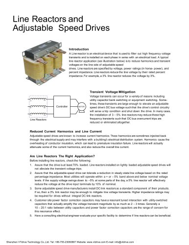
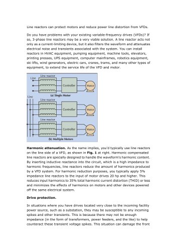
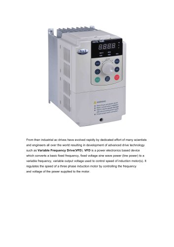
Line Reactors and AC Drives
Quite often, line and load reactors are installed on AC drives without a solid understanding of why or what
the positive and negative consequences are for adding this piece of hardware. The purpose of this
document is to provoke some thought on the part of the person(s) responsible for the successful
installation of the drive, and to provide some guidelines as to if, where and when a reactor is needed and
what size reactor to use.
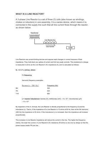
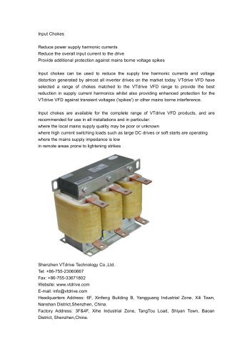
What Is A Reactor:
Let’s first define what a reactor is. Essentially a reactor is an inductor. Physically it is simply a coil of wire
that allows a magnetic field to form around the coil when current flows through it. When energized, it is an
electric magnet with the strength of the field being proportional to the amperage flowing and the number
of turns. A simple loop of wire is an air core inductor. More loops give a higher inductance rating. Quite
often some ferrous material such as iron is added as a core to the winding. This has the effect of
concentrating the lines of magnetic flux there by making a more effective Inductor.
Going back to basic AC circuit theory, an inductor has the characteristic of storing energy in the magnetic
field and is reluctant to a change in current. The main property of a reactor is its inductance and is
measured in henrys, millihenrys or microhenrys. In a DC circuit (such as that of the DC bus in an AC
drive), an inductor simply limits the rate of change of current in the circuit since current in an inductor
wants to continue to flow at the given rate for any instant in time. That is to say, an instantaneous
increase or decrease in applied voltage will result in a slow increase or decrease in current. Conversely, if
the rate of current in the inductor changes, a corresponding voltage will be induced. If we look at the
equation V=L (di/dt) for an inductor where V is voltage, L is inductance and (di/dt) is the rate of change of
current in amps per second, we can see that a positive rise in current will cause a voltage to be induced.
This induced voltage is opposite in polarity to the applied voltage and proportional to both the rate of rise
of current and the inductance value. This induced voltage subtracts from the applied voltage thereby
limiting the rate of rise of current. This inductance value is a determining factor of the reactance. The
reactance is part of the total impedance for an AC circuit. The equation for the reactance of an inductor is
XL = 2¶FL. Where XL is inductive reactance in Ohms, F is the applied frequency of the AC source and L is
the inductance value of the reactor. As you can see, the reactance and therefor the impedance of the
reactor is higher with a higher inductance value. Also, a given inductance value will have a higher
impedance at higher frequencies. Thus we can say that in addition to limiting the rate of rise in current, a
reactor adds impedance to an AC circuit proportional to both its inductance value and the applied
frequency.
Side-Effects of adding a Reactor:
Like most medication there are side-effects to using a reactor. Though these issues should not prevent
the use of a reactor when one is required, the user should be aware of and ready to accommodate these
effects. Since a reactor is made of wire (usually copper) wound in a coil, it will have the associated losses
due to wire resistance. Also, if it is an Iron core inductor (as in the case of most reactors used in power
electronics) it will have some “eddy current” loss in the core due to the changing magnetic field and the
iron molecules being magnetically realigned. In general a reactor will add cost and weight, require space,
generate heat and reduce efficiency.
Sometimes the addition of a line reactor can change the characteristics of the line you are connected to.
Other components such as power factor correction capacitors and stray cable capacitance can interact
with a line reactor causing a resonance to be set up. AC drives have exhibit a relatively good power factor
and do not require the use of correction capacitors. In fact, power factor correction capacitors often do
more harm than good where AC drives are present. For the most part, power factor correction capacitors
should never be used with a drive. You may find that the addition of a reactor completes the required
components for a line resonance where none previously existed, especially where power factor correction
capacitors are present. In such cases either the capacitor or the inductor must be removed.