عضویت
عضویت  ورود اعضا
 راهنمای خرید


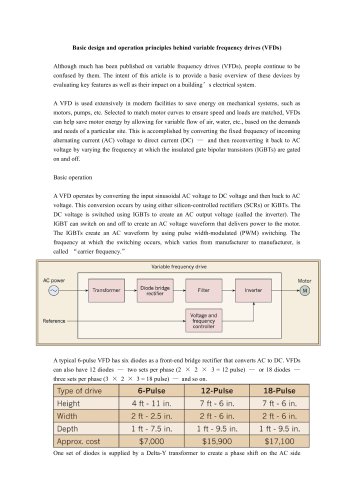
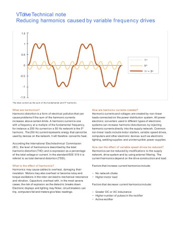
VTdrive - The Basics of Current Sensors0 pages
The Basics of Current Sensors
Current sensors are either open- or closed-loop. Open-loop current sensors measure AC and DC
currents and provide electrical isolation between the circuit being measured and the output of the sensor
(the primary current is measured without electrical contact with the primary circuit, providing galvanic
isolation). Less expensive than their closed-loop cousins, open-loop current sensors are generally
preferred in battery-powered circuits given their low-operating power requirements and small footprint
features.
Closed-loop sensors measure AC and DC currents and provide electrical isolation. They offer fast
response, high linearity, and low temperature drift. The current output of the closed-loop sensor is
relatively immune to electrical noise. The Closed- Loop sensor is sometimes called a ‘Zero-Flux’ sensor
because its Hall-Effect sensor feeds back an opposing current into a secondary coil, wound on the
magnetic core to zero the flux produced in the magnetic core by the primary current. Closed-loop sensors
are often the sensor of choice when high accuracy is essential.
Let’s now take a closer look at both types, starting with open-loop sensors.
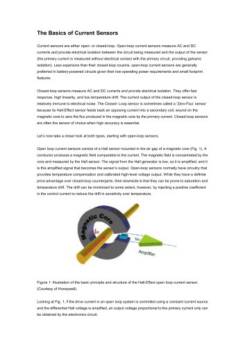
Open loop current sensors consist of a Hall sensor mounted in the air gap of a magnetic core (Fig. 1). A
conductor produces a magnetic field comparable to the current. The magnetic field is concentrated by the
core and measured by the Hall sensor. The signal from the Hall generator is low, so it is amplified, and it
is this amplified signal that becomes the sensor’s output. Open-loop sensors normally have circuitry that
provides temperature compensation and calibrated high-level voltage output. While they have a definite
price advantage over closed-loop counterparts, their downside is that they can be prone to saturation and
temperature drift. The drift can be minimized to some extent, however, by injecting a positive coefficient
in the control current to reduce the drift in sensitivity over temperature.
Figure 1: Illustration of the basic principle and structure of the Hall-Effect open loop current sensor.
(Courtesy of Honeywell).
Looking at Fig. 1, if the drive current in an open loop system is controlled using a constant current source
and the differential Hall voltage is amplified, an output voltage proportional to the primary current only can
be obtained by the electronics circuit.