عضویت
عضویت  ورود اعضا
 راهنمای خرید


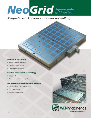
permanent magnetic lifters0 pages

WEN magnetics
nnnnWENtechnology
nnnn8411 Garvey Drive
nnnnSuite 117
nnnnRaleigh, NC 27616
nnnnTel : 919-954-1004
nnnnFax: 919-954-1009
nnnnwww.wenmag.com
nnnnCi
nnnnLIFTING MAGNETS
nnnnM LX-250/500/1000/2000
nnnnUSER'S MANUAL - Metric
nnnnREAD THIS MANUAL CAREFULLY BEFORE USING THE LIFTING MAGNET
nnnnIMPORTANT! The capacity of a lifting mag net depends on various factors which influence magnetic performance. These instructions must be carefully
nnnnread and observed.
nnnnFACTORS INFLUENCING CAPACITY OF LIFTING MAGNETS
nnnnBesides weight, there are additionalcharacteristicsofthe load which must be considered to evaluate the capacity of lifting magnets. Lifting magnets use magnetic
nnnnforce to grip the load so, for this reason, the load must be composed of a magnetic material (for example, iron).
nnnnThe magnetic force is formed in lines offeree (magnetic flux) which run from the North to the South poles of the lifting magnet. Any condition which impedes or
nnnnlimits the free flow of the magnetic flux reduces the lifting capacity. There are four major factors which impede the flow of magnetic flux.
nnnn1 The contact surface:
nnnnThe magnetic flux of the lifting magnet easily passes through iron
nnnnbut does not pass easily through air or non-magnetic materials. If a
nnnnseparation (air gap) is caused between the lifting magnet and the
nnnnload, the magnetic flux is weakened and this reduces the lifting force.
nnnnOxide, paint, dirt, paper, plastic or a rough surface finish produce an
nnnnair gap and therefore a reduction in the lifting capacity.
nnnn2 The thickness of the load:
nnnnThe magnetic flux of the lifting magnet needs a minimum thickness
nnnnof iron to work (the iron becomes saturated if a given flux density -
nnnnnumber of lines of flux per unit volume - is exceeded).
nnnnWhen the piece does not have this minimum thickness the lifting
nnnnforce is reduced.
nnnn3 The length and width of the load:
nnnnAs the load becomes longer and/or wider, there is a tendency for it to droop
nnnnaway from the lifter creating a contact surface that is curved and not flat.
nnnnThis curvature results in an air gap between the lifting magnet and the load
nnnnresulting in a reduction of lifting capacity, especially with thin pieces.
nnnnWhen this happens the lifting force is reduced.
nnnn4 The composition of the load:
nnnnLow carbon steels are good magnetic conductors, for example non-alloy
nnnnsteel 0.1-0.3%C such as 1018 / A36. However, steels with high carbon
nnnnand/or alloy contents have reduced magnetic properties and this reduces
nnnnthe lifting force. Heat treatment affecting the structure of the steel also
nnnnreduces magnetic performance - harder steels have lower lifting force
nnnncapacity and an increased tendency to retain residual magnetism.
nnnnThe nominal force of these lifting magnets is for non-alloy steel 0.1-0.3%C.
nnnnINSTALLING HANDLE
nnnnAlong with this lifting magnet, a handle is supplied that must be installed
nnnnbefore operation. Follow these instructions:
nnnn- Fit the handle (1 ) in the hole (3) of the shaft of the lifter.
nnnn- Check that the notch (2) in the handle lines up with the tapped hole
nnnn(4) of the shaft.
nnnn- Next insert the Allen stud (5) in the hole (4).
nnnnAttention! Ensure that the end of the stud (5) fully engages in the notch
nnnn(2) of the handle and secures it in place. Check that the locking shaft
nnnn(6) protrudes from the shaft as shown and blocks the handle from
nnnnaccidental rotation.
"