عضویت
عضویت  ورود اعضا
 راهنمای خرید


MLZ0 pages

72
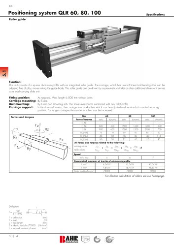
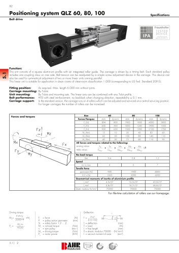
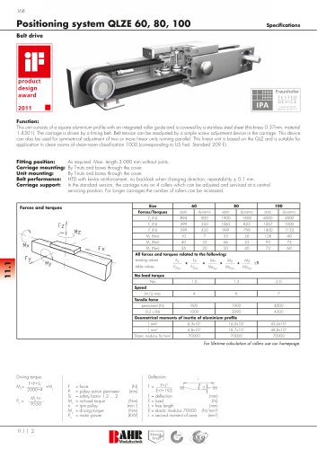
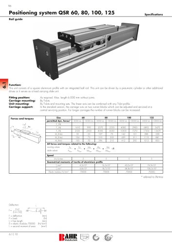
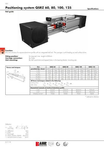
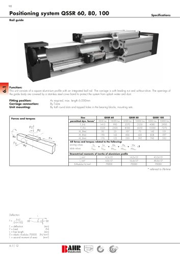
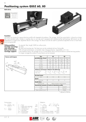
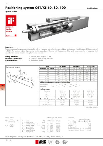
Positioning system MLZ 60, 60S, 80, 80S, 100
Specifications
3.1
Belt drive
Function:
This linear unit consists of an aluminium square profile with integrated, hardened steel guide rods. The carriage, which has internal linear ball
bearings, that can be adjusted free of play, is driven along the guide rods by a timing belt. The advantage of this system is that the belt is guided
within the profile, ensuring that the belt is always tight and thus enabling the system to be operated e.g. when lying on its side. The pulleys have
maintenance-free ball bearings. Belt tension can be readjusted by a simple screw adjustment device in the carriage. This device can also be used
for symmetrical adjustment of two or more linear units running parallel.
Fitting position:
Carriage mounting:
Unit mounting:
Belt type:
As required, max. length 6.000 mm without joints.
By T-slots.
By T-slots or tapped holes in the bearing block, mounting sets.
HTD with steel reinforcement, no backlash when changing direction,
Size
Forces and torques
Fz
Mx
MLZ 60 S
MLZ 80
MLZ 80 S
MLZ 100
Forces/Torques
dynamic
statisch
dynamisch
static
dynamic
static
dynamic
static
dynamic
894
800
894
800
1900
1800
1900
1800
4000
3800
Fy (N)
3000
2000
4100
3100
3000
2000
4600
3600
8000
6500
Fz (N)
Mz
static
Fx (N)
1700
1100
2160
1600
1700
1100
3000
1800
3600
2200
230
Mx (Nm)
43
88
65
90
55
170
140
300
90
70
190
140
110
80
270
230
400
270
Mz (Nm)
My
67
My (Nm)
Fx
Fy
MLZ 60
repeatability: ± 0,1 mm.
120
100
230
170
150
120
300
220
750
500
All forces and torques relate to the following:
existing values
table values
Fy
Fz
+
Fydyn
Fzdyn
+
Mx
Mxdyn
+
My
Mydyn
+
Mz
Mzdyn
≤1
No-load torque
Nm
0,6
0,7
0,9
1,2
1,4
5
7
6
8
10
Speed
(m/s) max
Tensile force
permanent (N)
900
900
1900
1900
4000
0,2 s (N)
1000
1000
2090
2090
4300
Geometrical moments of inertia of aluminium profile
lx mm4
4,83x10⁵
4,83x10⁵
17,49x10⁵
17,49x10⁵
39,4x10⁵
ly mm
5,03x10
5,03x10
18,02x10
18,02x10
43,5x10⁵
E-Modulus N/mm²
70000
70000
70000
70000
70000
4
5
5
5
5
For life-time calculation of rollers use our homepage.
Driving torque:
F P S
Ma= * * i +Mn
2000*π
Pa =
Ma*n
9550
3.1 | 34
Deflection:
F
P
Si
Mn
n
Ma
Pa
=
=
=
=
=
=
=
force
pulley action perimeter
safety factor 1,2 ... 2
no-load torque
rpm pulley
driving torque
motor power
(N)
(mm)
(Nm)
(min-1)
(Nm)
(KW)
f =
f =
F=
L=
E=
I =
F*L3
E*I*192
deflection
load
free length
elastic modulus 70000
second moment of area
(mm)
(N)
(mm)