عضویت
عضویت  ورود اعضا
 راهنمای خرید


Acousto Optic Mode Lockers0 pages
tr.row {}
td.cell {}
div.block {}
div.paragraph {}
.font0 { font:17.00pt "Arial", sans-serif; }
.font1 { font:12.00pt "Georgia", serif; }
.font2 { font:21.00pt "Microsoft Sans Serif", sans-serif; }
.font3 { font:8.00pt "Times New Roman", serif; }
.font4 { font:9.00pt "Times New Roman", serif; }
Brimrose Corporation ofAmerica
19 Love ton Circle
Sparks, MD 21152-9201 USA
Phone: +1 410 472-7070
Fax: +1 410 472-7960
E-Mail offic e s@brimrose .com
Web: http://www.brimro se .c o m
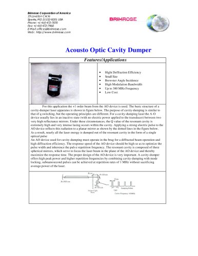
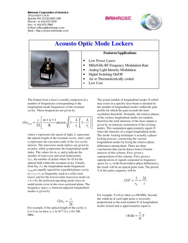
Acousto Optic Mode Lockers
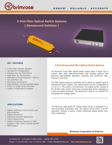
features/applications
low power lasers
Օ mhz/ghz rf frequency modulation rate
analog light intensity modulation
Օ digital switching on/off
air or thermoelectrically cooled
mm rfiiiivr-:'-i
Օ low cost
The Output from a laser is usually comprised of a number of frequencies corresponding to the longitudinal mode frequencies of the resonant cavity. These frequencies are given by
The actual number of longitudinal modes N which may exists in a specific laser beam is dictated by the number of longitudinal modes within the gain profile for which the gain exceeds the laser oscillation threshold. Normally, the relative phases of the various longitudinal modes are random, therefore the total intensity of the laser output is given by an intensity summation of the existing modes. This summation approximately equals N times the intensity of a single longitudinal mode. The mode- locking technique is actually a phase-locking process, connecting the various longitudinal modes by fixing the relative phase differences among them. There are three conclusions that can be drawn from a Fourier analysis of this scheme. First, given a superposition of this scheme. First, given a superposition of signals separated in frequency space by v0 (with fixed relative phase differences), the result will be an optical pulse train. The period T of this pulse sequence will be
(3)T = ± = 2L
(1)v =
m+n+1
1 - -
r2J
arccos
2 L
r1 a
where c represents the speed of light, L represents the optical le ngth of the resonant cavity, and r1 and r2represents the curvature radii of the two cavity mirrors. The transverse mode indices are given by m and n, while q represents the longitudinal mode index. The values for m, n, and q indicate the number of transverse and axial nodal points (i.e., the number of points where E= 0) for the optical field within the resonant cavity. Clearly, from Eq. (1), the longitudinal mode frequencies vmnqare equally spaced for a parallel-planes cavity (r1 = r2 = ל, as frequently used in a solid-state laser), and for the lowest-order transverse mode (m = n = 0), the preferred operating mode since no nodal points exist in the cross-sectional plane. The frequency space v0 between adjacent longitudinal modes is given by
v
0
c
(2)v = 2L
For example, if the optical length of the cavity is L=1.5 m, we have v0 = 3x 10 8/ (2 x 1.5)= 100 MHz.
For example, T=10 ns when v0=100 MHz. Second, the width t of each light pulse is inversely proportional to the total number N of longitudinal modes locked and is approximately equal to
(4) ~ࠗ T
N