عضویت
عضویت  ورود اعضا
 راهنمای خرید


Brushless DC motor0 pages
Small brushless DC motors_ Principles of opration The diffrences between a DC motor having a mechanical commutation system and a BLDC motor are mainly found in : - the product concept - the commutation of phase currents. From the user 's point of view, brushless DC motors follow the same equations as those with brushes: torque is proportional to current, speed depends on the voltage and the load torque. The commutation of brushless motors In the conventional DC motor commutation takes place mechanically through the commutator-and-brush system. In a BLDC motor, commutation is done by electronic means. In that case the instantaneous rotor position must be known in order to determine the phases to be energized. The angular rotor position can be known by: - using a position sensor (Hall sensor, optical encoder, resolver) - electronically analyzing the back-EMF of a non-energised winding. This is called sensorless commutation. Use of Hall sensors In general, BLDC motor have three phase windings. The easiest way is to power two of them at a time, using Hall sensors to know the rotor position. A simple logic allows for optimal energizing of the phases as a function of rotor position, just like the commutator and brushes are doing in the conventional DC motor. Use of an encoder or resolver The rotor position may also be known by use of an encoder or resolver. Commutation may be done very simply, similar to the procedure with Hall sensors, or it may be more complex by modulating sinusoidal currents in the three phases. This is called vector control, and its advantage is to provide a torque ripple of theoretically zero, as well as a high resolution for precise positioning. Use of Back-EMF analysis A third option requiring no position sensor is the use of a particular electronic circuit. The motor has only three hook-up wires, the three phase windings are connected in either triangle or star. In the latter case, resistors must be used to generate a zero reference voltage. With this solution the motor includes no sensors or electronic components and it is therefore highly insensitive to hostile environments. For applications such as hand-held tools, where the cable is constantly moved, the fact of just three wires is another advantage. The functioning of a sensorless motor is easy to understand. In all motors, the relation of back-EMF and torque versus rotor position is the same. Zero crossing of the voltage induced in the non-energised winding corresponds to the position of maximum torque generated by the two energized phases. This point of zero crossing therefore allows to determine the moment when the following commutation should take place depending on motor speed. This time interval is in fact equivalent to the time the motor takes to move from the position of the preceding commutation to the back-EMF zero crossing position. Electronic circuits designed for this commutation function allow for easy operation of sensorless motors.
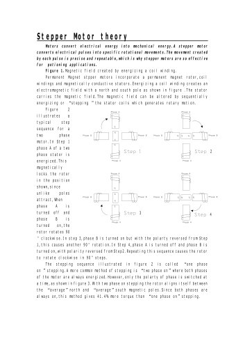
"