عضویت
عضویت  ورود اعضا
 راهنمای خرید


CERTIFLOW ®0 pages

CERTIFLOW ®
Look for the
stamp
ASME Compliant Rupture Discs
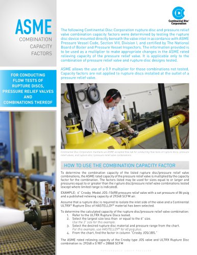
The ASME Boiler and Pressure Vessel Code, Section VIII, Division 1, specifies that
rupture disc devices, like all other pressure relief products, should be tested and
certified as to their flow characteristics, and that these certified values should be
used in flow and sizing calculations.
Rupture disc products manufactured in accordance with all applicable rules of ASME
Code Symbol Stamp (shown at left) on the
Code Section VIII, Division 1 must carry the
tag, as well as the certified flow resistance (KR) and minimum net flow area (MNFA) values.
The "NB" stamp acknowledges The National Board of Boiler and Pressure Vessel
Inspectors as the organization that certified the flow tests.
Continental Disc Corporation is accredited and authorized by the
Code Symbol Stamp for product built in acASME to utilize the
cordance with the requirements of the ASME Boiler and Pressure
Vessel Code, Section VIII, Division 1.
The complete line of CERTIFLOW® rupture discs meets all ASME
Code requirements, including KR and MNFA values. With the extensive line of CERTIFLOW rupture discs, there is one available to meet
most applications and operating conditions.
Certified KR values represent tested flow resistance values. Relief
systems can be designed or evaluated more precisely and safely if
certified flow resistance values are used, rather than industry practiced estimates. These estimates may not accurately reflect the flow
resistance of the rupture disc. Using the certified flow resistance
value, along with proper engineering practices, allows precise, efficient, and safe design of relief systems.
“K” values are pressure loss expressed as the number of velocity
heads and they are available for nearly all piping system devices and
components, including rupture discs.
Rupture disc devices should be included in the flow equation in
the same manner as all other system components to determine the
relieving capacity of the entire relief system. Design engineers are
provided with certified KR values:
•t which enable the designer to meet ASME Code Section VIII,
Division 1 for relief system design
• which may permit a reduction in pipe size and associated piping
costs when utilized during a relief system design
•t for use when evaluating relief systems where two-phase flow
may occur
•t for use when re-evaluating existing relief systems to complyt
with design documentation requirements of OSHA CFR 1910.119,"
Process Safety Management of Highly Hazardous Chemicals."
Two Ways to Use a Certified Flow Resistance Factor
To confirm relief capacity requirements in a sole relief device
system
To confirm a rupture disc/PRV combination follows the
“3% Rule”
Combining the certified flow resistance
(KR) with the K values of other piping
components (shown in example A) allows
Example A
the design engineer to accurately calculate
and evaluate a relief system’s flow capacity.
Even for simple relieving systems that can be
evaluated with the coefficient of discharge method
Example B
(8 & 5 rule), utilizing the certified flow resistance (KR)
along with the associated K values for the other piping
components (shown in example B) will allow for the flow capacity to
be more accurately evaluated.
The system shown might be
designed new, or it might be reevaluated to comply with OSHA
CFR 1910.119, which requires
that systems be designed with
“recognized and generally accepted engineering practices.” In the past,
an estimated value for the flow resistance of the rupture disc would be
used for calculations.
Combining the certified flow resistance value (KR) with the K values
of the other piping components, a design engineer can now accurately
evaluate this system’s nonrecoverable pressure loss.
To specify a rupture disc device to comply with the ASME Code:
1)t Select the most appropriate rupture disc model for your
application. Use the Rupture Disc Selection Guide (Bulletin
#1-1100) or contact your local representative for assistance
2)t Find the type, holder, media, required options, and estimated
size in Table I or II
3) Find the corresponding MNFA in Table III
4)t Use the KR and MNFA values to confirm the flow characteristics
of your relieving system.
For assistance with flow of fluids calculation, consult Crane Technical
Paper No. 410. There is also a variety of software titles that will automate
your flow of fluid calculations. Be certain that your evaluation uses
proper engineering practices such as including all piping system
components into your flow calculations and multiplying the calculated
relieving capacity by a factor of 0.90 or less as specified in ASME Code
Section VIII, Division 1.
A copy of Continental Disc Corporation's Certificate of Authorization
to use the
Code Symbol Stamp can be found on our website
at www.contdisc.com. There you will also find the most current
CERTIFLOW data.