عضویت
عضویت  ورود اعضا
 راهنمای خرید


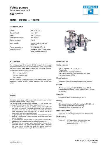
Non-clogging Pump0 pages

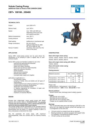
Non-clogging Pump
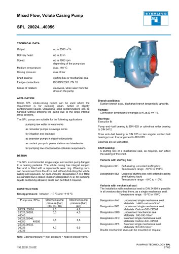
DBS 3216...30040
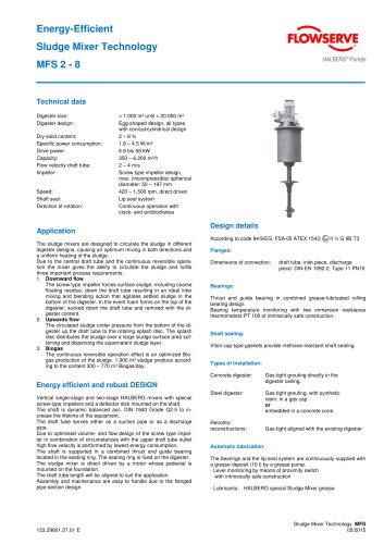
TECHNICAL DATA
Output: up to 1200 m3/h
Delivery head: up to 100 m
Speed: up to 3600 rpm
depending of the pump size and
material execution
Medium temperature: max. 110 °C
Casing pressure: 10 bar
Shaft sealing: stuffing box or mechanical seal
Flange connections: PN 10
Sense of rotation: clockwise, when seen from the
drive on the pump
APPLICATION
Series DBS volute-casing pumps can be used where the
requirement is for pumping dirty liquids or liquids with solids.
Sewage plants: Storm water, pre-filtered sewage,
industrial effluents
Chemical plants: Chemical effluents, brines and lies, milk
of lime, crystal sludge, filter material,
plastic suspensions
Rolling mills: Scale-contaminated water from steel and
copper rolling mills
Foundries and iron Effluents and sludges from dust and
and steel works: arrester plants
Construction industry: Mixtures of water and cement and water
from excavation ditches
Paper and cellulose Paper, chemical pulp and mechanical
pulp
industry: suspensions up to 6% absolutely dry
Sugar mills: Carbonation juice, concentrated juice,
milk of lime
Food industry: Thick mash, fruit and potato slices
(parings)
DESIGN
Process type, single-stage, volute casing pumps with design
features and nominal rating to ISO2858/EN22858 and enlarged
sizes
The process design permits dismantling of the complete bearing
unit towards the drive end, without the pump casing having to be
disconnected from the piping. If a spacer coupling is used it is
also unnecessary to disconnect the motor.
CONSTRUCTION
Casing pressure: Max. 10 bar between -10 º C and +120 ºC
Please note: Casing pressure = Inlet pressure + shut off head.
Max. test pressure 16 bar
Branch positions:
Suction branch axial, discharge branch radial upwards.
Flanges:
Connection dimensions of flanges DIN 2501 PN 10 .
Flanges can be supplied drilled to ANSI
Optional the pump can be supplied with a flange adapter
piece on the suction side (see sectional drawing, pos. 72.20)
Bearings:
Execution B:
Pump end: one cylindrical roller bearing to DIN 5412
Drive end: one deep groove ball bearing to DIN 625
The bearings are grease lubricated
Execution C:
Pump end: one cylindrical roller bearing to DIN 5412
Drive end: one deep groove ball bearing to DIN 625
The bearings are oil lubricated
Execution S:
Pump end: one cylindrical roller bearing to DIN 5412
Drive end: two angular contact ball bearings in Oarrangement.
The bearings are grease lubricated
Execution T:
Pump end: one cylindrical roller bearing to DIN 5412
Drive end: two angular contact ball bearings in Oarrangement.
The bearings are oil lubricated
Shapes of impellers:
Double channel
impeller (code Z) or
triple channel
impeller (code D)
Free-flow impeller
(code F)
If required, the sealing clearance gap on the suction side of
pumps fitted with double and triple channel and wear plates can
be arranged for flushing.