عضویت
عضویت  ورود اعضا
 راهنمای خرید


FS-600 - No-Moving-Parts Flow Switch0 pages
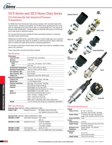
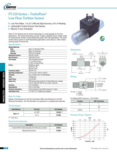
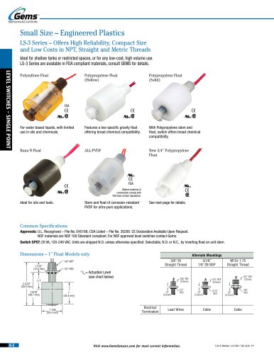
FS-600 Series – No Moving Part, Thermal
Dispersion Flow Switch
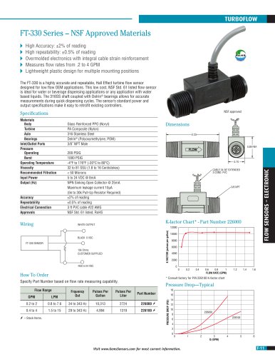
Flow Rate Settings: 0.1 GPM to 11 GPM (0.5 LPM to 41 LPM)
Port Size: 1/2˝ to 1-1/2˝ (NPT or G thread)
Ro H S
G
EM
®
S CO PLIAN
M
T
Ro H S
G
EM
®
S CO PLIAN
M
T
Setting Type: Fixed
The FS-600 series uses proven thermal dispersion technology to provide a robust no
moving part flow switch even without filtration. The solid state sensor is compatible
with both conductive and non-conductive fluids. Suitable for fluids with particulates or
slurries, and is immune to changes in media viscosity. The straight through switch is
designed for a long life and can be mounted in any orientation and can handle a wide
range of flow rates. No moving parts means years of reliable service.
Specifications
FLOW SWITCHES
Wetted Materials
Probe
Flow Body
Operating Pressure (Max.)
Operating Temperature
Power on Delay Time
Response Time
Inlet/Outlet Ports
t
Operating Voltage
Current Consumption
Switch Contact Rating
Switch Logic
Ingress Protection
Set point Accuracy
Set point Differential
Electrical Termination
Approvals
303 Stainless Steel
316 Stainless Steel
363 PSIG (25 bar)
-14° F to 140°F (-10°C to 60°C)
15 Seconds Max (Output On)
10 Seconds Max.
1/2˝, 3/4˝, 1˝, 1-1/2˝ NPT
1/2˝, 3/4˝, 1˝, 1-1/2˝ G Internal
24 Vdc or 24Vac +/- 15%
Less than 50mA
30Vac@45mA, 42Vdc @65mA
Normally Open
IP65
15%
20% (Max.)
M12 x 1 (4-Pin) (1 meter cable included)
CE, RoHS
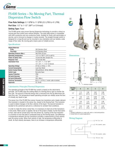
Dimensions
3˝
(76 mm)
LABEL
ØC
B
NPTF
2 PLACES
D
A
SENSING ELEMENT
Calorimetric Principle/Thermal Dispersion
The operating principle of the FS-600 flow switch is based on the calorimetric
principle. The FS-600 uses the cooling effect of a flowing fluid or gas to monitor the
flow rate. The amount of thermal energy that is removed from the tip determines the
local flow rate. This temperature-based operating principle can reliably sense the flow
of virtually any liquid or gas.
The sensor tip of the FS-600 flow sensor houses two transistors and a heater element.
One transistor is located in the sensor tip, closest to the flowing fluid. This transistor
is used to detect changes in the flow velocity of the liquid. The second transistor is
bonded to the cylindrical wall and is a reference for ambient fluid conditions.
In order to make the sensor sense flow, it is necessary to heat one of the transistors
in the probe. When power is applied, the tip of the probe is heated. As the fluid starts
to flow, heat will be carried away from the sensor tip. Cooling of the first transistor
is a function of how fast heat is conducted away by the flowing liquid. The difference
in temperature between the two transistors provides a measurement of fluid velocity
past the sensor probe. When fluid velocity is high, the temperature differential is
small. As fluid velocity decreases, there is an increase in temperature differential.
Port Size
NPTF
A
B
C
D
1/2˝
1.13
(28.7)
2.65
(67.3)
0.62
(15.8)
3.06
(77.8)
3/4˝
1.50
(38.1)
2.75
(69.9)
0.824
(20.9)
4.00
(101.6)
1˝
1.50
(38.1)
2.75
(69.9)
1.05
(26.7)
4.00
(101.6)
1-1/2˝
2.25
(57.1)
3.00
(76.2)
1.61
(40.9)
4.25
(107.9)
Notes:
1. Standard calibration is in water with units in a horizontal position.
2. Consult Gems for special applications.
Wiring Diagram
Pin 1 (V+) - red
Pin 2 (switch) - green
Pin 4 (switch) - yellow
Pin 3 (V-) - blue
G-2
Visit www.GemsSensors.com for most current information.
"