عضویت
عضویت  ورود اعضا
 راهنمای خرید


Backwashing Membranes0 pages
Technical Brief
LIQUID PROCESS FILTERS
GRAVER TECHNOLOGIES
1-888-353-0303
www.graver tech.com
TB–004
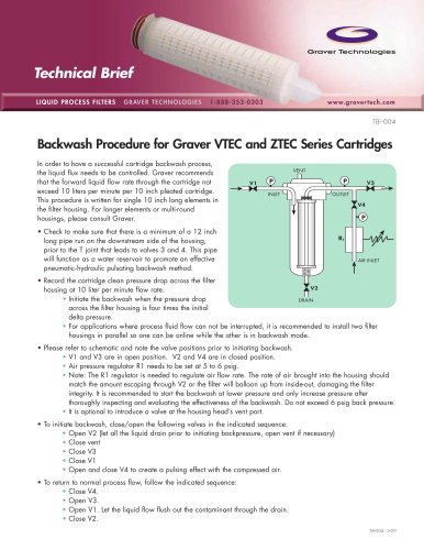
Backwash Procedure for Graver VTEC and ZTEC Series Cartridges
In order to have a successful cartridge backwash process,
the liquid flux needs to be controlled. Graver recommends
that the forward liquid flow rate through the cartridge not
exceed 10 liters per minute per 10 inch pleated cartridge.
This procedure is written for single 10 inch long elements in
the filter housing. For longer elements or multi-round
housings, please consult Graver.
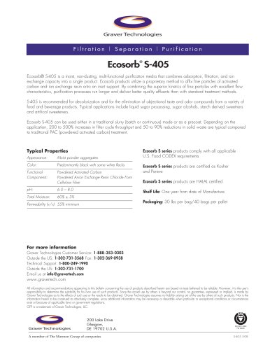
VENT
V3
V1
INLET
OUTLET
• Check to make sure that there is a minimum of a 12 inch
long pipe run on the downstream side of the housing,
prior to the T joint that leads to valves 3 and 4. This pipe
will function as a water reservoir to promote an effective
pneumatic-hydraulic pulsating backwash method.
V4
R1
AIR INLET
• Record the cartridge clean pressure drop across the filter
V2
housing at 10 liter per minute flow rate.
• Initiate the backwash when the pressure drop
DRAIN
across the filter housing is four times the initial
delta pressure.
• For applications where process fluid flow can not be interrupted, it is recommended to install two filter
housings in parallel so one can be online while the other is in backwash mode.
• Please refer to schematic and note the valve positions prior to initiating backwash.
• V1 and V3 are in open position. V2 and V4 are in closed position.
• Air pressure regulator R1 needs to be set at 5 to 6 psig.
• Note: The R1 regulator is needed to regulate air flow rate. The rate of air brought into the housing should
match the amount escaping through V2 or the filter will balloon up from inside-out, damaging the filter
integrity. It is recommended to start the backwash at lower pressure and only increase pressure after
thoroughly inspecting and evaluating the effectiveness of the backwash. Do not exceed 6 psig back pressure.
• It is optional to introduce a valve at the housing head’s vent port.
• To initiate backwash, close/open the following valves in the indicated sequence:
• Open V2 (let all the liquid drain prior to initiating backpressure, open vent if necessary)
• Close vent
• Close V3
• Close V1
• Open and close V4 to create a pulsing effect with the compressed air.
• To return to normal process flow, follow the indicated sequence:
• Close V4.
• Open V3.
• Open V1. Let the liquid flow flush out the contaminant through the drain.
• Close V2.
TB-004 3-09