عضویت
عضویت  ورود اعضا
 راهنمای خرید


TL6 0 pages

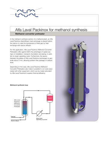
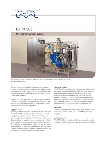
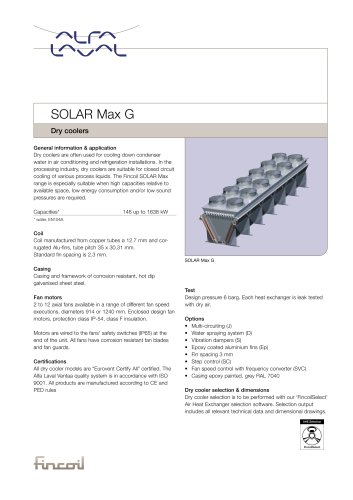
TL6
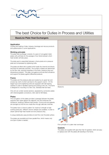
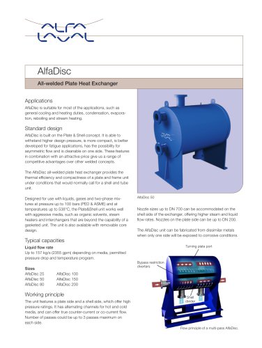
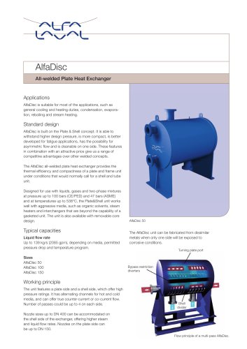
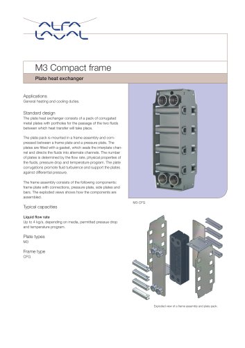
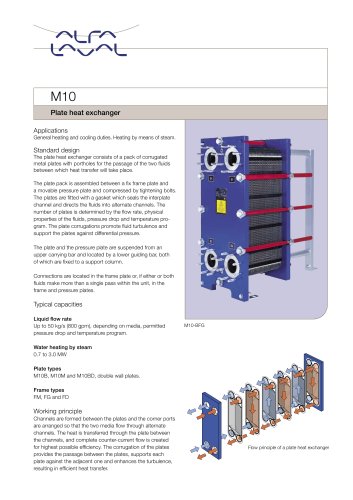
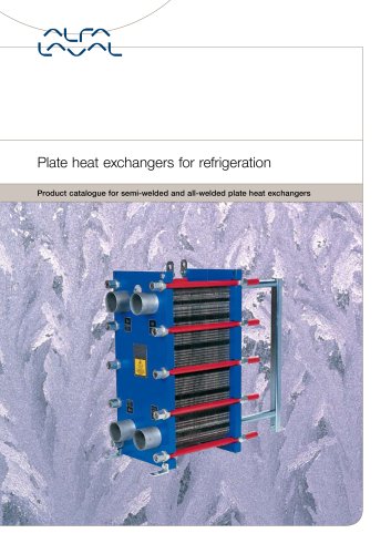
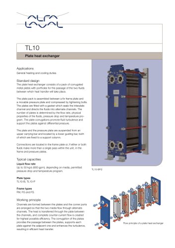
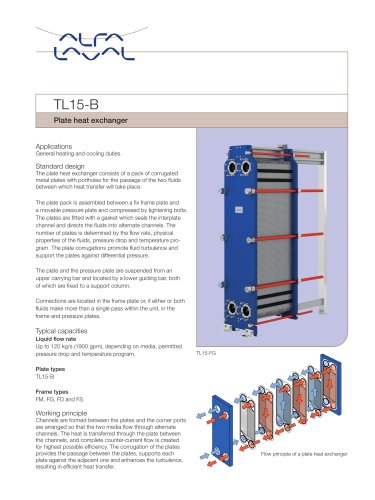
Flow principle of a plate heat exchanger
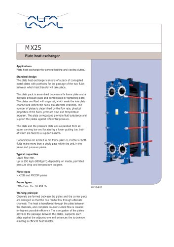
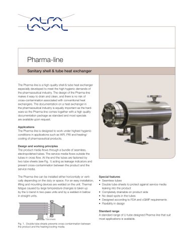
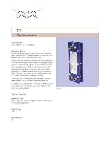
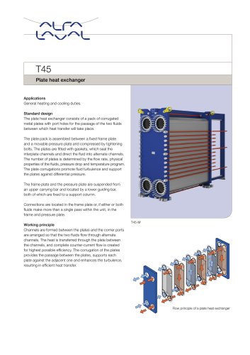
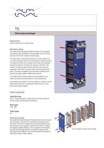
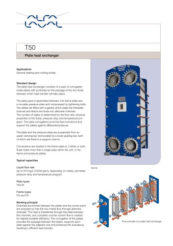
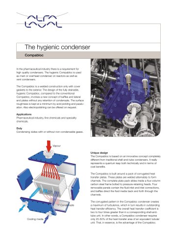
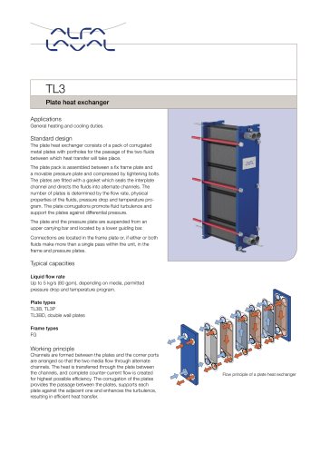
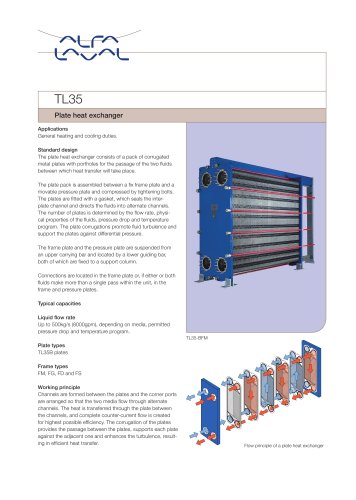
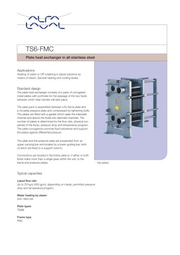
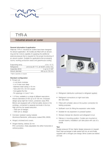
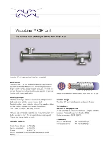
Plate heat exchanger
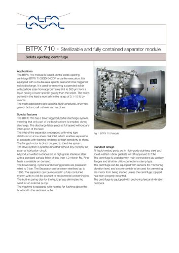
Applications
General heating and cooling duties.
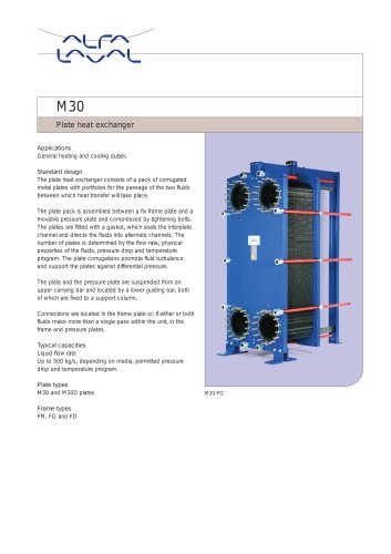
Standard design
The plate heat exchanger consists of a pack of corrugated
metal plates with portholes for the passage of the two fluids
between which heat transfer will take place.
The plate pack is assembled between a fix frame plate and
a movable pressure plate and compressed by tightening bolts.
The plates are fitted with a gasket which seals the interplate
channel and directs the fluids into alternate channels. The
number of plates is determined by the flow rate, physical
properties of the fluids, pressure drop and temperature program.
The plate corrugations promote fluid turbulence and
support the plates against differential pressure.
The plate and the pressure plate are suspended from an
upper carrying bar and located by a lower guiding bar, both
of which are fixed to a support column.
Connections are located in the frame plate or, if either or both
fluids make more than a single pass within the unit, in the
frame and pressure plates.
Typical capacities
Liquid flow rate
Up to 20 kg/s (317 gpm), depending on media, permitted
pressure drop and temperature program.
Plate types
TL6B
Frame types
FM, FG and FD
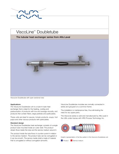
Working principle
Channels are formed between the plates and the corner ports
are arranged so that the two media flow through alternate
channels. The heat is transferred through the plate between
the channels, and complete counter-current flow is created
for highest possible efficiency. The corrugation of the plates
provides the passage between the plates, supports each
plate against the adjacent one and enhances the turbulence,
resulting in efficient heat transfer.