عضویت
عضویت  ورود اعضا
 راهنمای خرید


ACS7100 pages

ACS710
120 kHz Bandwidth, High Voltage Isolation
Current Sensor with Integrated Overcurrent Detection
Features and Benefits
Description
▪ Industry-leading noise performance with greatly improved
bandwidth through proprietary amplifier and filter design
techniques
▪ Small footprint package suitable for space-constrained
applications
▪ 1 mΩ primary conductor resistance for low power loss
▪ High isolation voltage, suitable for line-powered
applications
▪ User-adjustable Overcurrent Fault level
▪ Overcurrent Fault signal typically responds to an
overcurrent condition in < 2 μs
▪ Integrated shield virtually eliminates capacitive coupling
from current conductor to die due to high dV/dt voltage
transients
▪ Filter pin capacitor improves resolution in low bandwidth
applications
▪ 3 to 5.5 V, single supply operation
▪ Factory trimmed sensitivity and quiescent output voltage
▪ Chopper stabilization results in extremely stable quiescent
output voltage
▪ Ratiometric output from supply voltage
The Allegro™ ACS710 current sensor provides economical
and precise means for current sensing applications in industrial,
commercial, and communications systems. The device is offered
in a small footprint surface mount package that allows easy
implementation in customer applications.
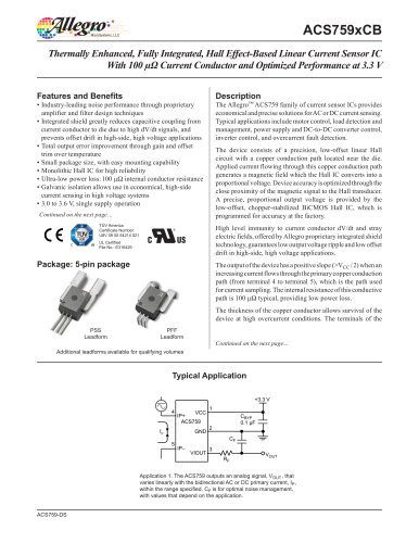
Package: 16-pin SOIC Hall Effect IC
Package (suffix LA)
The ACS710 consists of a precision linear Hall sensor integrated
circuit with a copper conduction path located near the surface
of the silicon die. Applied current flows through the copper
conduction path, and the analog output voltage from the Hall
sensor linearly tracks the magnetic field generated by the
applied current. The accuracy of the ACS710 is maximized
with this patented packaging configuration because the Hall
element is situated in extremely close proximity to the current
to be measured.
High level immunity to current conductor dV/dt and stray
electric fields, offered by Allegro proprietary integrated shield
technology, results in low ripple on the output and low offset
drift in high-side, high voltage applications.
The voltage on the Overcurrent Input (VOC pin) allows
customers to define an overcurrent fault threshold for the device.
When the current flowing through the copper conduction path
(between the IP+ and IP– pins) exceeds this threshold, the open
drain Overcurrent Fault pin will transition to a logic low state.
Factory programming of the linear Hall sensor inside of the
ACS710 results in exceptional accuracy in both analog and
digital output signals.
The internal resistance of the copper path used for current
sensing is typically 1 mΩ, for low power loss. Also, the current
conduction path is electrically isolated from the low voltage
Approximate Scale 1:1
Continued on the next page…
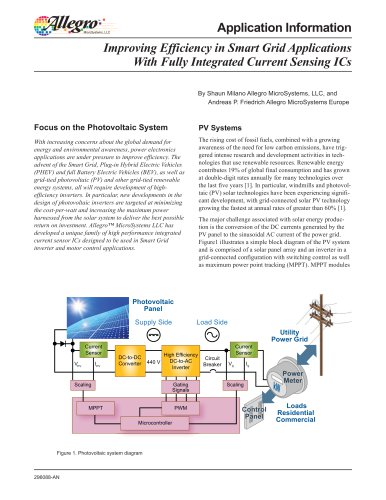
Typical Application Circuit
1
2
3
4
IP
5
6
7
8
IP+
IP+
IP+
FAULT_EN
ACS710
VOC
VCC
IP+
FAULT
IP–
VIOUT
IP–
FILTER
IP–
VZCR
IP–
GND
ACS710-DS, Rev. 9
16 Fault_EN
RH
VCC
RH, RL
15
14
12
11
RPU
COC
COC
0.1 μF
B
CF
1 nF
A
Noise and bandwidth limiting filter capacitor
Fault delay setting capacitor, 22 nF maximum
A
Use of capacitor required
B
Use of resistor optional, 330 kΩ recommended.
If used, resistor must be connected between
¯ ¯¯¯ ¯ pin and VCC.
¯ L¯
¯
FAU¯ T
VIOUT
10
9
CF
RL
13
Sets resistor divider reference for VOC
"