عضویت
عضویت  ورود اعضا
 راهنمای خرید


KB Signal Isolator0 pages

fl^^ "The Right Control for Your Application" 12095 NW 39 Street, Coral Springs, FL 33065-2516
IT4 Zj Telephone: 954-346-4900; Fax: 954-346-3377
t^wKB Electronics, Inc._www.kbelectronics.com
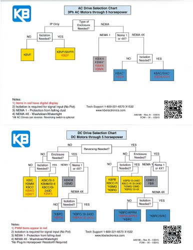
SIAC 2G Signal Isolator (Part No. 9600) Installation Instructions
The SIAC 2G Signal Isolator is Designed to be Used with the Following 2G KBAC Series Drives
KBAC-24D (Part Nos. 9987G* & 9988G*), KBAC-27D (Part Nos. 9520G* & 9521G*),
__^§APj29JPart_Nos._95J_8_&^
*The software revision code is printed on the bottom right side of the 2.5" X 7/8" silver ratings label, which is located on the top of the drive.
Kit Includes: SIAC Signal Isolator, Installation Instructions, Interconnecting Ribbon Cable, and two Snap-In Mounting Bases.
1 DESCRIPTION
The SIAC Signal Isolator provides an isolated interface between non-isolated signal sources and the drive. It is used with the KBAC
Series drives to isolate, amplify, and condition DC voltage and current signals from any source (tach-generators, transducers, PLCs, and
potentiometers). It also provides an isolated input to control motor direction and an isolated power supply for transducer or potentiometer
operation. All input connections are isolated from the AC line and motor wiring. The SIAC installs easily into the drive with a snap-in
mounting base and is wired with a connector.
The main features of the SIAC include voltage or current signal inputs. Other features include a power on LED, a barrier terminal block to
facilitate wiring, multi-turn trimpots (MAX, OFFSET), and a selectable jumper for voltage or current signal input selection. An optional
accessory for use with the SIAC is an Auto/Manual Switch (Part No. 9481), which selects a signal input from either the SIAC or the Main
Speed Potentiometer of the drive.
2 FEATURES
■ Isolated Switching: Provides isolation for PLC open collector or contact switching.
■ Isolated +5V Power Supply: Used to power a transducer or to supply voltage for Main Speed Potentiometer operation.
■ Power On LED: Provides indication that power is applied.
■ Trimpot Adjustments (Multi-Turn): Maximum Speed (MAX) and Signal Offset (OFFSET).
■ Signal Input Selection (Jumper J1): Selects voltage or current signal inputs.
■ Optional Accessory: Auto/Manual Switch (Part No. 9481) selects a signal input from either the SIAC or the Main Speed Potentiometer.
■ Easy Installation: A snap-in Mounting Base and Interconnecting Ribbon Cable are provided for easy installation into the drive.
Table 1
Parameter | Specifications | Factory Setting |
Maximum Speed Trimpot (MAX) Input Voltage Range (Volts DC) | 0 to 2.5 thru 0 to 25 | Oto 5 |
Offset Trimpot (OFFSET) Range (% of MAX Trimpot Setting) | 0-±50 | 0 |
Input Current Range (milliamps DC) | 4-20 | |
Forward and Reverse Input Switch Types | Dry Contact or Open Collector | |
+5V Power Supply Maximum Load Current Rating (milliamps DC) | 25 | |
Potentiometer Operation (kO) | 5 | |
Input/Output Linearity (%) | 0.1 | |
Thermal Drift (millivolts per °C) | 0.4 | |
Operating Temperature Range (°C / °F) | 0-45/32- 113 |
Figure 1
SIAC Signal Isolator Layout
<{V -5V OV FWD REV SIG1 C0M1
O O O O O O G
O
XT
Jumpers are shown in factory set positions.
J1: Sets the drive for operation with a voltage or current input signal.
' MAX: Maximum Speed adjustment trimpot.
' OFFSET: Signal Offset adjustment trimpot.
' TB1: Signal Input, Direction Switch, and Main Speed Potentiometer connections.
' PWR: Power On LED.
' C0N1: Used for the Ribbon Cable to connect the SIAC to the Drive.
(A40149) - Rev. D00 - 4/21/2009
Page 1 of 6
"