عضویت
عضویت  ورود اعضا
 راهنمای خرید


V-Series Pump Protector0 pages
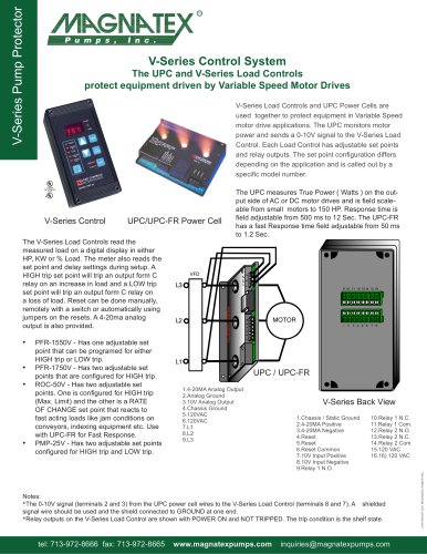
V-Series Pump Protector
V-Series Control System
The UPC and V-Series Load Controls
protect equipment driven by Variable Speed Motor Drives
V-Series Load Controls and UPC Power Cells are
used together to protect equipment in Variable Speed
motor drive applications. The UPC monitors motor
power and sends a 0-10V signal to the V-Series Load
Control. Each Load Control has adjustable set points
and relay outputs. The set point configuration differs
depending on the application and is called out by a
specific model number.
V-Series Control
UPC/UPC-FR Power Cell
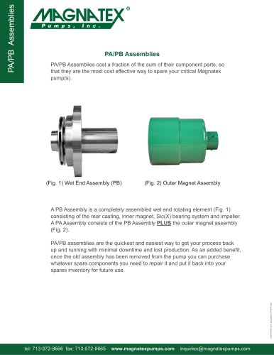
The V-Series Load Controls read the
measured load on a digital display in either
HP, KW or % Load. The meter also reads the
set point and delay settings during setup. A
HIGH trip set point will trip an output form C
relay on an increase in load and a LOW trip
set point will trip an output form C relay on
a loss of load. Reset can be done manually,
remotely with a switch or automatically using
jumpers on the resets. A 4-20ma analog
output is also provided.
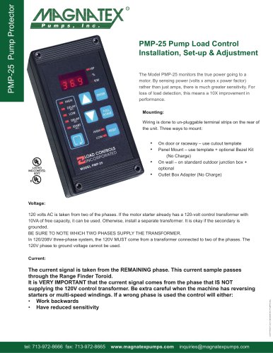
The UPC measures True Power ( Watts ) on the output side of AC or DC motor drives and is field scaleable from small motors to 150 HP. Response time is
field adjustable from 500 ms to 12 Sec. The UPC-FR
has a fast Response time field adjustable from 50 ms
to 1.2 Sec.
•t PFR-1550V - Has one adjustable set
•t
•t
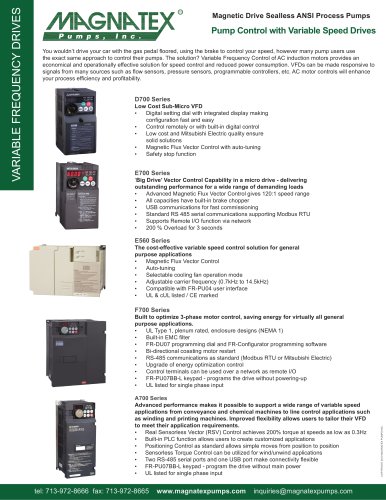
UPC / UPC-FR
1.4-20MA Analog Output
2.Analog Ground
3.10V Analog Output
4.Chassis Ground
5.120VAC
6.120VAC
7.L1
8.L2
9.L3
V-Series Back View
1.Chassis / Static Ground
2.4-20MA Positive
3.4-20MA Negative
4.Reset
5.Reset
6.Reset Common
7.10V Input Positive
8.10V Input Negative
9.Relay 1 N.O.
10.Relay 1 N.C.
11.Relay 1 Com.
12.Relay 2 N.O.
13.Relay 2 N.C.
14.Relay 2 Com.
15.120 VAC
16.16) 120 VAC
Notes:
*The 0-10V signal (terminals 2 and 3) from the UPC power cell wires to the V-Series Load Control (terminals 8 and 7). A shielded
signal wire should be used and the shield connected to GROUND at one end.
*Relay outputs on the V-Series Load Control are shown with POWER ON and NOT TRIPPED. The trip condition is the shelf state.
tel: 713-972-8666 fax: 713-972-8665
www.magnatexpumps.com
inquiries@magnatexpumps.com
COPYRIGHT 2011 MAGNATEX PUMPS INC.
•t
point that can be programed for either
HIGH trip or LOW trip.
PFR-1750V - Has two adjustable set
points that are configured for HIGH trip.
ROC-50V - Has two adjustable set
points. One is configured for HIGH trip
(Max. Limit) and the other is a RATE
OF CHANGE set point that reacts to
fast acting loads like jam conditions on
conveyors, indexing equipment etc. Use
with UPC-FR for Fast Response.
PMP-25V - Has two adjustable set points
configured for HIGH trip and LOW trip.