عضویت
عضویت  ورود اعضا
 راهنمای خرید


AC GENERATOR CURRENT DIFFERENTIAL GUARD0 pages
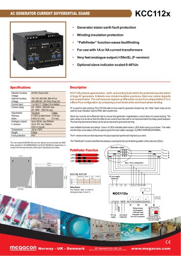
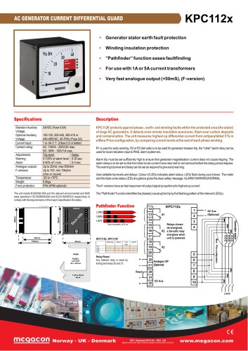
AC GENERATOR CURRENT DIFFERENTIAL GUARD
KCC112x
• Generator stator earth fault protection
• Winding insulation protection
• ”Pathfinder” function eases faultfinding
• For use with 1A or 5A current transformers
• Very fast analogue output (<50mS), (F-version)
• Optional slave indicator scaled 0-40%In
Description
Specifications
Standard Auxiliary
Voltage:
Optional Auxiliary
Voltage:
Current Input::
Contact rating:
24VDC (Fuse 0,5A)
Adjustments:
Warning:
Alarm:
Analogue outputs:
F-versions
100-120, 200-240, 380-415 or
440-460VAC, 40-70Hz (Fuse 2A)
1 or 5A C.T. (Class 0,5 or better)
AC: 100VA - 250V/2A max.
DC: 50W - 100V/1A max.
Trip level:
Delay:
0-100% of alarm level 0-30 sec.
0-40% of I nom.
0-3 sec.
Up to 20mA, max 500ohm
Up to 10V, min 10kohm
KCC112E protects against phase-, earth- and winding faults within the protected area (the stator)
of large AC generators. It detects even minute insulation punctures, flash-over carbon deposits
and contamination. The unit measures highest up differential current from antiparallelled CTs in
a Merz-Price configuration, by comparing current levels at the end of each phase winding.
R1 is used for early warning. R2 or R3 (fail safe) is to be used for generator breaker trip, the "other" alarm relay can be
used for local indication input to PMS, alarm system etc.
Alarm trip must be set sufficiently high to ensure that generator magnetisation current does not cause tripping. The
alarm delay is to be set so that the initial inrush current have returned to normal level before the delay period elapses.
The warning trip level and delay can be set as required to give early warning.
(other on request)
Temperature:
Weight:
Front protection:
User settable trip levels and delays. Colour of LEDs indicates alarm status. LEDs flash during count-down. The meter
and the triple-zone status LEDs at a glance gives the clear safety message: ALARM/ WARNING/NORMAL
-20 to +70ºC
0.6kgs
IP21
The F-versions have an fast response mAoutput signal proportional to highest up current.
The "Pathfinder" function identifies the phase(s) causing the trip by the flashing pattern of the relevant LED(s).
The unit meets IEC60092-504 and the relevant environmental and EMC
tests specified in IEC60068/60092 and IEC61000/60533 respectively, to
comply with the requirements of the major Classification Societies.
Generator stator
Pathfinder Function
l
k
l
k
L1(R)
75mm
l
k
l
k
L2(S)
l
k
l
k
L3(T)
L
O
A
D
Merz - Price configuration
100mm
Red indicates LED on
85mm
KCC112E, KCC112F
Warning
Alarm
Fail
safe
Latch
R1
R2
R3
DIN Rail
Relay Reset
Any latched relay is reset by
linking terminals 12 and 13.
AC aux supply
(Optional)
~
~
1
2
3
4
5 6 7 8 9 10
KCC112x
Cabel with
RJ12 plug
14 15
11 12 13
16 17 18 19 20 21 22 23 24
R1
+ -
DC aux
supply
Norway - UK - Denmark
+ -
mA output
(Optional)
REF: Datasheet.KCC112x - REV: 1.00
Megacon reserves the right to make any changes to the information at any time
R2
Relays shown
de-energised,
a fail-safe relay
energises when
the unit is powered.
R3
%In
40
20
AL ARM
W AR N I N G
D IF F ER E N TIA L
C U RR E N T G U AR D
0
Optional slave indicator
with LEDs (DIN96)
www.megacon.com
"