عضویت
عضویت  ورود اعضا
 راهنمای خرید


Servo Amp Module Upgrade Notice to 8XX Series This document provides information and differences on upgrading previous series of Servo Amplifier Modules to the -8XX series module.0 pages
Oilgear Automation d AIM e | TECHNICAL DOCUMENT | dNV7liMCCKHMV9 | 1 1 |
SERVO AMPLIFIER MODULE UPGRADE NOTICE
PURPOSE AND SCOPE
The SERVO AMPLIFIER MODULE L404563-000 thru
799, manufactured by The Oilgear Company has been
discontinued and replaced with SERVO AMPLIFIER
MODULE, part number L404563-8XX series. This pub-
lication explains the user differences.
GENERAL
The balance and main gain adjustments of the SERVO
AMPLIFIER MODULE, part number L404563-8XX
series are made via two (2) pairs of hexadecimal rotary
switches, which are accessed through the front of the
module cover. The left switch of each pair is the most
significant digit, or coarse adjustment; the right switch
is the least significant digit, or fine adjustment.
The switches are hexadecimal, meaning they have 16
positions each. The positions increase in value from
"0" to "F", as the switches are rotated clockwise. When
the right switch (least significant digit) roll over from
"F' to "0" clockwise, the left switch (most significant
digit) must be incremented one clockwise increment.
When the right switch (least significant digit) rolls over
from "0" to "F" counterclockwise, the left switch (most
significant didgit) must be incremented one counter-
clockwise increment. This provides 256 different com-
binations of settings.
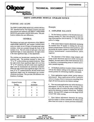
Original Switch Setting | +1 Step Increment |
0 0 3 F 5 5 E F | 0 1 4 0 5 6 F 0 |
Example:
A. AMPLIFIER BALANCE
1. ' Set the balance switches to the hexadecimal pre-
liminary numbers 7F. This is the mid-point, or zero set-
ting of the amplifier 256 divided by 2 = 128 (7F) mid
point of +/-range.
2. If the system balance requires adjustment, increasing
the numbers from 7F equates to rotating the old style
balance potentiometer clockwise (more positive), and
decreasing the number equates to rotating the old style
balance potentiometer counterclockwise (more
negative).
3. The placement of the balance range jumpers and
pump stroke determine physical stroke increment
obtained. For each coarse or fine switch increment there
is, therefore a corresponding pump or control move-
ment (neutral response).
4. All feedback positions on pump volume commands
will use this balance setting as the minimum, home or
neutral position for referencing amplifier commands.
5. Some applications require critical, precise balance
adjustments. Many applications utilize hydraulic
valves to bypass flows or pressures resulting from
slight off sets from precise non-balance settings.
6. One-way pump applications may utilize the balance
adjustments to keep the pump from crossing to the
non-delivery side or to insure the pump is held slightly
against the minimum or neutral volume stop. Typically
against the stop LVDT voltages are in the range of 0.05
to 0.25 VDC while running.
7. Since balance adjustments determine the starting
point for stroke or volume commands, the balance may
affect final full stroke or volume positions attainable.
Telephone: (414) 327-1700 OILGEAR Reissued: June, 1996
Fax: (414) 327-0532 2300 So. 51st. Street E005
v Milwaukee, Wl USA 53219
"