عضویت
عضویت  ورود اعضا
 راهنمای خرید


Modular Electronics Section0 pages
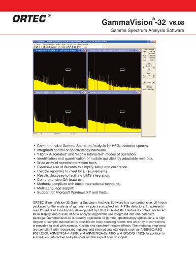
ORTEC
®
Electronics Standards
and Definitions
NIM and CAMAC Standards for Modular Instrumentation
Most of the nuclear electronic instrumentation manufactured by ORTEC is designed in accordance with either the NIM standard or the
CAMAC standard for modular instrumentation. Both of these international standards encompass a wide range of mechanical and
electrical definitions to provide cost and convenience advantages to users of the instruments.
Two of the most important advantages of the NIM and CAMAC concepts are flexibility and interchangeability. The user may configure
the optimum system for a particular application, and later easily restructure the instruments as required for different experiments or
measurements. In addition, an existing system can be updated with a few new modules, thereby augmenting the value of
instrumentation on hand. As experimental demands increase, or as advancing technology makes new instruments available, new
modules can be added to the system with assurance of compatibility.
Both the NIM and CAMAC standards incorporate modular instruments that plug into a “bin” or “crate,” and derive their power from a
standard power supply attached to the rear of the bin (crate). The CAMAC standard differs from the NIM standard in two important
ways. First, the CAMAC crate has a built-in, digital data bus to provide computer communications with the modules. Second, the
narrowest CAMAC modules are exactly half the width of the minimum NIM module width. Power plug adapters are available from
several manufacturers to permit NIM modules to slide into a CAMAC crate and derive their power from the CAMAC power supply.
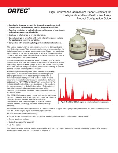
Some of the ORTEC products are manufactured in “bench-top” or “stand-alone” packages for applications that demand a specific
solution. In such cases the unit typically draws power from 90 V ac, 117 V ac, or 240 V ac, and generates its own dc voltages
internally. The rechargeable, battery-operated, field-portable spectrometers are an example of this packaging. For the stand-alone and
bench-top packages the analog and digital signals also conform to the NIM, ECL, and TTL standards described on the following
pages.
Many of the NIM, stand-alone, and bench-top instruments provide their own interface to a personal computer. Such interfaces can be
made via the IEEE-488, RS-232-C, Ethernet, USB, and printer-port standards, or by the ORTEC Dual-Port Memory Interface. A
number of the data control and acquisition products are also available on cards that plug into the PCI bus inside the personal
computer.
NIM Standard
All ORTEC NIM instrumentation conforms to the May 1990 Revision of the NIM standard [formerly TID 20893 (Rev) and NIM/GPIB].
Please refer to DOE/ER-0457T, U.S. NIM committee, May 1990; Standard NIM Instrumentation System, NTIS, U.S. Department of
Commerce, Springfield, Virginia 22161.
CAMAC Standard
All ORTEC CAMAC instrumentation conforms to the CAMAC standard: IEEE Standard 583-1982, reaffirmed 1994, IEEE Standard
Modular Instrumentation and Digital Interface System (CAMAC), Institute of Electrical and Electronics Engineers, Inc., P.O. Box 1331,
445 Hoes Lane, Piscataway, NJ 08855-1331.
Linear and Logic Signal Standards and Connections
Because many ORTEC instruments utilize both linear and logic signals, it is important to distinguish between linear and logic
connections when setting up the equipment. The amplitude of a linear signal contains information about the charge or energy
deposited by a detected event. Therefore, linear signals vary over a range of amplitudes. The analysis of linear signal amplitudes from
an instrument reveals the pulse-height spectrum of the detected events. In contrast, logic signals have a fixed amplitude and shape.
They are used to count events, provide timing information, and to control the function of subsequent instruments in a system. Both
linear and logic signal connections are made by coaxial cables and standard BNC, LEMO, or SMA connectors. Some logic signal
connections are made with ribbon or multi-wire cable terminated in multi-pin connectors.
Slow Linear Signals
Slow linear signals generally have rise times longer than 50 ns, and durations ranging from 0.5 to 100 µs. In ORTEC modules, these
signals conform to the NIM-Standard Preferred Practices for 0 to 10-V spans. Slow linear signals may be unipolar and positive in
polarity, or bipolar with the positive polarity occurring first. In either case, it is the range from 0 to +10 V that is analyzed for pulse
amplitude information.
Standard polarity and span do not apply to the linear signal between the preamplifier and the amplifier. This signal must be variable in
span and polarity to accommodate particular applications. However, ORTEC charge-integrating preamplifiers typically furnish a 50-µs
(or greater) time-constant tail pulse to the main amplifier. The main amplifier accommodates this standardized input pulse with a
compatible pole-zero cancellation circuit. In addition, ORTEC main amplifiers designed for energy or pulse-height spectroscopy accept
either positive or negative input polarities.
Most ORTEC instruments provide the slow linear output signals through a very low source impedance, typically <1 Ω. The low
impedance allows connection of almost any load without loss of signal amplitude. For example, a 100-Ω load may be driven to the full