عضویت
عضویت  ورود اعضا
 راهنمای خرید


DETAILS OF INVOLUTE GEARING0 pages
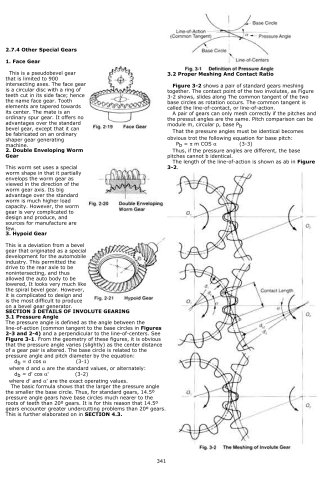
2.7.4 Other Special Gears
1. Face Gear
This is a pseudobevel gear
that is limited to 900
intersecting axes. The face gear
is a circular disc with a ring of
teeth cut in its side face; hence
the name face gear. Tooth
elements are tapered towards
its center. The mate is an
ordinary spur gear. It offers no
advantages over the standard
bevel gear, except that it can
be fabricated on an ordinary
shaper gear generating
machine.
2. Double Enveloping Worm
Gear
This worm set uses a special
worm shape in that it partially
envelops the worm gear as
viewed in the direction of the
worm gear axis. Its big
advantage over the standard
worm is much higher load
capacity. However, the worm
gear is very complicated to
design and produce, and
sources for manufacture are
few.
3. Hypoid Gear
This is a deviation from a bevel
gear that originated as a special
development for the automobile
industry. This permitted the
drive to the rear axle to be
nonintersecting, and thus
allowed the auto body to be
lowered, It looks very much like
the spiral bevel gear. However,
it is complicated to design and
is the most difficult to produce
on a bevel gear generator.
SECTION 3 DETAILS OF INVOLUTE GEARING
3.1 Pressure Angle
The pressure angle is defined as the angle between the
line-of-action (common tangent to the base circles in Figures
2-3 and 2-4) and a perpendicular to the line-of-centers. See
Figure 3-1. From the geometry of these figures, it is obvious
that the pressure angle varies (slightly) as the center distance
of a gear pair is altered. The base circle is related to the
pressure angle and pitch diameter by the equation:
db = d cos a (3-1)
where d and a are the standard values, or alternately:
db = d' cos a' (3-2)
where d' and a' are the exact operating values.
The basic formula shows that the larger the pressure angle
the smaller the base circle. Thus, for standard gears, 14.5º
pressure angle gears have base circles much nearer to the
roots of teeth than 20º gears. It is for this reason that 14.5º
gears encounter greater undercutting problems than 20º gears.
This is further elaborated on in SECTION 4.3.
3.2 Proper Meshing And Contact Ratio
Figure 3-2 shows a pair of standard gears meshing
together. The contact point of the two involutes, as Figure
3-2 shows, slides along The common tangent of the two
base circles as rotation occurs. The common tangent is
called the line-of-contact, or line-of-action.
A pair of gears can only mesh correctly if the pitches and
the pressut angles are the same. Pitch comparison can be
module m, circular p, base Pb
That the pressure angles must be identical becomes
obvious trot the following equation for base pitch:
Pb = p m COS a (3-3)
Thus, if the pressure angles are different, the base
pitches cannot b identical.
The length of the line-of-action is shown as ab in Figure
3-2.
341