عضویت
عضویت  ورود اعضا
 راهنمای خرید


LOADING

SCREW GEARS (Crossed Helical Gears)0 pages
نسخه متنی
"
"
| The formulas of a standard helical rack are similar to those of Table 6-6 with only the normal coefficient of profile shift xn=0. To mesh a helical gear to a helical rack, they must have the same helix angle but with opposite hands. The displacement of the helical rack, /, for one rotation of the mating gear is the product of the radial pitch, pt, and number of teeth. | 7.1.2 Module Because of the possibility of different helix angles for the gear pair, the radial modules may not be the same. However, the normal modules must always be identical. 7.1.3 Center Distance The pitch diameter of a crossed-helical gear is given by Equation (6-7), and the center distance becomes: 2 v cosplcosp2' v ' Again, it is possible to adjust the center distance by manipulating the helix angle. However, helix angles of both gears must be altered consistently in accordance with Equation (7-1). 7.1.4 Velocity Ratio Unlike spur and parallel shaft helical meshes, the velocity ratio (gear ratio) cannot be determined from the ratio of pitch diameters, since these can be altered by juggling of helix angles. The speed ratio can be determined only from the number of teeth, as follows: veloc i ty ratio = i = ___ (7-3) | |||||||||||||||||||||||||||||||||||||||||||||||||
| (6-13) | ||||||||||||||||||||||||||||||||||||||||||||||||||
| cos ^ | ||||||||||||||||||||||||||||||||||||||||||||||||||
| According to the equations of Table 6-7, let radial pitch pt= 8 mm and displacement I = 160 mm. The radial pitch and the displacement could be modified into integers, if the helix angle were chosen properly. In the axial system, the linear displacement of the helical rack, /, for one turn of the helical gear equals the integral multiple of radial pitch. | ||||||||||||||||||||||||||||||||||||||||||||||||||
| (6-14) | ||||||||||||||||||||||||||||||||||||||||||||||||||
| I = nzmt | ||||||||||||||||||||||||||||||||||||||||||||||||||
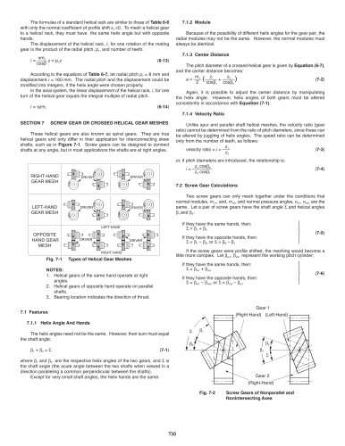
| SECTION 7 SCREW GEAR OR CROSSED HELICAL GEAR MESHES These helical gears are also known as spiral gears. They are true helical gears and only differ in their application for interconnecting skew shafts, such as in Figure 7-1. Screw gears can be designed to connect shafts at any angle, but in most applications the shafts are at right angles. | ||||||||||||||||||||||||||||||||||||||||||||||||||
| or, if pitch diameters are introduced, the relationship is: | ||||||||||||||||||||||||||||||||||||||||||||||||||
| z1 cosp2 z2 cosߟ1 | ||||||||||||||||||||||||||||||||||||||||||||||||||
| (7-4) | ||||||||||||||||||||||||||||||||||||||||||||||||||
| i - | ||||||||||||||||||||||||||||||||||||||||||||||||||
| RIGHT-HAND GEAR MESH | ||||||||||||||||||||||||||||||||||||||||||||||||||
| 7.2 Screw Gear Calculations | ||||||||||||||||||||||||||||||||||||||||||||||||||
| Two screw gears can only mesh together under the conditions that normal modules, mn1, and, mn2, and normal pressure angles, an1, an2, are the same. Let a pair of screw gears have the shaft angle E and helical angles p1and p2: | ||||||||||||||||||||||||||||||||||||||||||||||||||
| LEFT-HAND GEAR MESH | ||||||||||||||||||||||||||||||||||||||||||||||||||
| DRIVER | ||||||||||||||||||||||||||||||||||||||||||||||||||
| If they have the same hands, then: E = P1 + P2 If they have the opposite hands, then: E = P1 _ P2, or E = P2 _ P1 | ||||||||||||||||||||||||||||||||||||||||||||||||||
| LEFT-HAND | ||||||||||||||||||||||||||||||||||||||||||||||||||
| (7-5) | ||||||||||||||||||||||||||||||||||||||||||||||||||
| OPPOSITE HAND GEAR MESH | ||||||||||||||||||||||||||||||||||||||||||||||||||
| ^DRIVER RIGHT-HAND | ||||||||||||||||||||||||||||||||||||||||||||||||||
| If the screw gears were profile shifted, the meshing would become a little more complex. Let pw1, pw2represent the working pitch cylinder; | ||||||||||||||||||||||||||||||||||||||||||||||||||
| Fig. 7-1 Types of Helical Gear Meshes NOTES: 1. Helical gears of the same hand operate at right angles. 2. Helical gears of opposite hand operate on parallel shafts. 3. Bearing location indicates the direction of thrust. | ||||||||||||||||||||||||||||||||||||||||||||||||||
| If they have the same hands, then: ^ = Pw1 + Pw2 If they have the opposite hands, then: 2 = Pw1 _ Pw2, or E = pw2 _ Pw1 | ||||||||||||||||||||||||||||||||||||||||||||||||||
| (7-6) | ||||||||||||||||||||||||||||||||||||||||||||||||||
| Gear 1 (Right-Hand) (Left-Hand) | ||||||||||||||||||||||||||||||||||||||||||||||||||
| 7.1 Features | ||||||||||||||||||||||||||||||||||||||||||||||||||
| 7.1.1 Helix Angle And Hands | ||||||||||||||||||||||||||||||||||||||||||||||||||
| The helix angles need not be the same. However, their sum must equal the shaft angle: | ||||||||||||||||||||||||||||||||||||||||||||||||||
| Pi + P2 = 2 | (7-1) | |||||||||||||||||||||||||||||||||||||||||||||||||
| where and p2are the respective helix angles of the two gears, and E is the shaft angle (the acute angle between the two shafts when viewed in a direction paralleling a common perpendicular between the shafts). Except for very small shaft angles, the helix hands are the same. | ||||||||||||||||||||||||||||||||||||||||||||||||||
| Gear 2 (Right-Hand) | ||||||||||||||||||||||||||||||||||||||||||||||||||
| Fig. 7-2 Screw Gears of Nonparallel and Nonintersecting Axes | ||||||||||||||||||||||||||||||||||||||||||||||||||