عضویت
عضویت  ورود اعضا
 راهنمای خرید


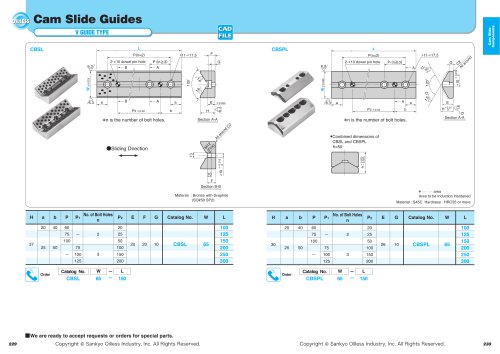
Spherical Bush Set:SBSF,SBSS,SBSR0 pages

OUTLINE OF SPHERICAL BUSHING UNIT
Outline of Spherical Bushing Unit
OILLESS SPHERICAL BUSH SET
Spherical Bushing Set
RoHS
q For operation of spherical bushing unit
(1) Assembly and fixing method of unit
q Insert the unit at the specified position of the shaft.
w Fix the inner ring and the shaft with set screws.
e Fix the case with bolts.
SBSF (Inner Ring Flange Type)
SBSS (Inner Ring Straight Type)
SBSR (w , Outer Ring Only)
Make sure that the mating part for the unit is suitable for operating conditions.
Be careful that there is no foreign matter or step on the mounting surface.
• When three units or more are used, align the shaft correctly.
(The tolerance should be +/-0.25 mm.)
•
•
SBSF
SBSS
C
C
3.2
f
3.2
0.8
3.2
w
2-M
f
2-Ma
12
hd
0.8
0.8
S
(3) For thrust load
q If thrust load is applied, use the flange type inner ring. Solid lubricant is embedded at one side of the outer
ring.
w When a flange type is used, make assembly so that the flange area may match the solid lubricant surface at
the side.
0.8
0.8
h(d1-1)
hd1
hD
hd
0.8
0.8
hD1
hd1
hD
0˚
0˚
12
(2) Fixing method of shaft and inner ring
q Fix the inner ring at the position where the flange does not come in contact with the outer ring end. Fix it with
the clearance of 0.1 mm as a guideline. If interference between the inner ring flange and the outer ring end
due to thermal expansion/shrink of the shaft is concerned, adjust the clearance appropriately. (One straight
type screw per position is used)
w If the unit is used at a place or environment where vibration or impact is applied, provide seating at the set
screw position of the shaft with a file or borer.
J
h
J
3.2
h
w
S
eq
Recommended mating post tolerance is g6
eq
No. Description Qty
Material and remark
1
S45C
w Outer ring
1
Bronze with graphite oilless type(SO#50SP2)
Stopper pin for outer ring (SUJ2 1pce) is attached.
(4) For greasing
Grease groove is provided at the outer ring. Greasing can improve wear resistance and durability.
To minimize thrust from the inner flange type bushing, solid
lubricant is embedded on the outer ring edge.
q Inner ring
e Hexagon socket head screw 2
Inner ring
d
Tolerance
25
D1
C
S
J
0
o0.013
43.5
31
18.3
8.3
47.5
34
19.7
8.7
57.5 38.1 22.2
9.7
33
30
40
35
0
o0.016
50
40
(6) Measures for heat generation
If the unit is used at high temperature, thermal expansion (thrust direction) of the shaft occurs. If the flange type
inner ring is used, it is recommended to design the flange outside.
i0.021
0
Tolerance
28
20
(5) Accuracy and design of shaft
The recommended tolerance of the mating shaft is g6. Since the inner ring slides with the outer ring, material
and hardness of the shaft is not particularly important. Heat treatment of the shaft surface is not required either.
45
Outer ring
d1
i0.025
0
50
65
74.5 49.2 30.2 15.7
0
o0.019
70
Catalog No.
Tolerance
d1
Tolerance
h
Case
No.
4
47
o0.080
o0.105
28
i0.061
i0.040
20
204
20
4
52
22
205
25
5
5
62
25
206
6
6
72
27
207
7
80
60
29
208
7
85
65
29
209
45
8
90
30
210
50
5
4
6
8
8
10
33
o0.100
o0.130
o0.120
o0.155
40
i0.075
i0.050
50
70
i0.090
i0.060
Catalog No.
SBSF
SBSS
Outer ring
SBSR
d
30
35
40
d
SBSF
SBSR
Order
D
Ma
79.5 49.2 30.2 15.7
84.5 51.6 32.6 17.6
f
M
67.5 42.9 25.4 11.9
60
SCM435
35
35
0.8
137
3.2
Slide Unit
hd1
hD
3.2
h
138
"