عضویت
عضویت  ورود اعضا
 راهنمای خرید

Weight Loaded Pressure Reducing Valve0 pages

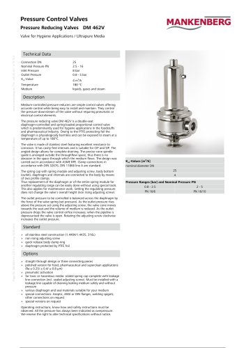
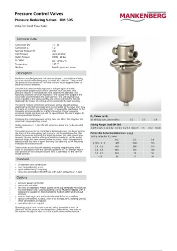
Pressure Control Valves
Pressure Reducing Valves DM 3, 4
MANKENBERG GmbH | Spenglerstraße 99 | D-23556 Lübeck
www.mankenberg.de | Tel. +49 (0) 451 - 8 79 75 0
Weight Loaded Pressure Reducing Valve
Technical Data
Connection DN
Nominal Pressure PN
Inlet Pressure
Outlet Pressure
Kvs-Value
Temperature
Medium
50 - 400
16 - 40
up to 40 bar
0.5 - 10 bar
32 - 1200 m3/h
280 °C
Liquids, Gases and Steam
Description
Medium-controlled pressure reducers are simple control valves offering
accurate control while being easy to install and maintain. They control
the pressure downstream of the valve without requiring pneumatic or
electrical control elements.
The DM 3 and DM 4 pressure reducers are medium-controlled
weighted-lever valves for medium to large volumes. These valves
require no auxiliary energy. Thanks to their integral control
characteristics they are very accurate. The time reponse is set by means
of an oil-filled damper.
DM 3 is a single seat, DM 4 a twin seat valve; both are
piston-controlled. The valves can be supplied with soft or hard seals.
The valve seat leakage meets the VDI/VDE Guideline 2174.
When the pipeline is depressurised the valve cone is kept in open
position by the weighted lever. As the outlet pressure rises a control
piston is pressurised via a pilot line, lifting the lever and moving the
valve cone towards the „closed“ position. During normal operation the
opening force of the weight and the closing force of the piston balance
each other and the pressure reducer operates continually. The outlet
pressure is kept constant irrespective of inlet pressure and flow volume.
The control pressure is set by changing the weight on the lever.
The maximum outlet pressure must not exceed 1.5 times the set
pressure, unless specified otherwise.
In the case of toxic or hazardous media a leakage line must be installed
to the control unit capable of draining leaking medium safely and
without pressure if the control element should become defective.
These valves are no shut-off elements ensuring a tight closing of the
valve. In accordance with the VDI/VDE guideline 2174 a leakage rate of
0.05 percent (DM 3) respectively 0.5 percent (DM 4) of the constant
volume flow is permitted for the valve in closed position.
Page No. DM 3, 4/2.1.135.1 - Standing 25.11.2013
The valves requires a sense line (to be installed on-site).
Options
» various seal materials suitable for your medium
» special versions on request
Operating instructions, know how and safety instructions must be
observed. All the pressure has always been indicated as overpressure.
We reserve the right to alter technical specifications without notice.
Kvs-Values [m3/h]
type nominal diameter DN
50
65
3 (E)
32
50
4 (E)
40
65
80
75
100
100
100
150
125
140
180
Suffix E = enlarged outlet
Kvs-Values [m3/h]
type nominal diameter DN
150
200
3 (E)
200
300
4 (E)
250
400
Suffix E = enlarged outlet
250
450
550
300
550
700
350
650
750
400
800
1200