عضویت
عضویت  ورود اعضا
 راهنمای خرید


ds-mvs0 pages

MVS t
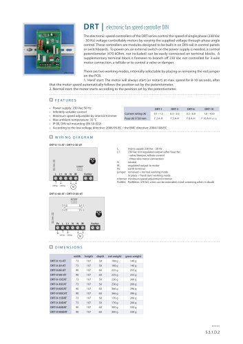
electronic fan speed controller for DIN rail
The MVS automatically controls the speed of single phase voltage controllable electric
motors (230 VAC - 50 Hz) with a 0-10 VDC or 20 mA control signal (standard). This makes it
possible to control these motors automatically with an external PD-controller, on remote
with a potentiometer, or a microprocessor with analog output. They are over voltage protected by a varistor and have a built in over current fuse.
These controllers are designed to be built in on DIN-rail in control panels or switchboards.
To power on, an external switch is needed. A supplementary terminal block is foreseen to
branch off 230 VAC not controlled for 3-wire motor connection, a telltale or to control a
valve or damper.
The working principle of this product series is based on the so-called zero crossing detection. An optotriac combined with a microprocessor ensures flawless and accurate control where motor noises are considerably lower.
There are two working modes, internally selectable by placing or removing the red jumper on the PCB.
1. ‘Hard’ start: The motor will always start (or restart) at max. speed for 8-10 seconds, after that the motor speed
automatically follows the control signal.
2. Normal start: the motor starts according to the control signal.
The CNVT-PWM-010V can easily be connected to provide a conversion of a PWM signal to a 0-10 V signal.
F e at u r e s
Power supply: 230 VAC - 50 Hz
According to the low voltage directive: 2006/95/EC / the EMC directive: 2004/108/EC
MVS-0-15xDT
Current rating (A)
Fuse F2 (A) 5*20
MVS-0-30xDT
MVS-0-60xDT
MVS-0-100xDT
0.1 - 1.5
0.1 - 3.0
0.5 - 6.0
0.5 - 10.0
F-3.15 A-H
F-5.0 A-H
F-10.0 A-H
F-16.0 A-H (6*32)
Executions:
x=”-”: as circuit board only
x=”D”: DIN rail mounting (EN 50-022)
x=”C”: fingerproof cover included
Wiring diagram
L
N
L1
LED
PT3
PT2
Sw1 Sw2 Sw3 Sw4
PT1
mains supply 230 VAC - 50 Hz
neutral
230 VAC unregulated output (Imax 2 A)
earth terminal (only for 3, 6 & 10 A)
M
Sw
GND
U
I
+V
Sw1
regulated output to motor
on/off switch
ground
control signal 0-10 VDC (input impedance 90 kOhm)
0-20 mA (input impedance 250 Ohm)
low voltage power supply: 12 VDC/1 mA for external trimmer
switch down = 0-10 V, up = 10-0 V (select increase or decrease
input voltage to control speed)
switch down = disable off-level, up = enable off-level
switch down = disable kickstart, up = enable kickstart
switch down = 0-20 mA, up = 0-10 V (select current/voltage)
max. speed adjustment trimmer, range: 165-230 V
min. speed adjustment trimmer, range: 60-160 V
off-level adjustment trimmer: 0-4 V or 10-6 V (depending on
Sw1)
green: normal operation.
blinking: standby (input signal < off level).
Sw2
Sw3
Sw4
PT1
PT2
PT3
LED
27/09/2013
S.3.2.D.1 137
"