عضویت
عضویت  ورود اعضا
 راهنمای خرید


Silicon Designs Model 2012 Analog Accelerometer Module0 pages

SPECIFICATIONS SUBJECT TO CHANGE WITHOUT NOTICE
Silicon Designs, Inc. ! 1445-NW Mall Street, Issaquah, WA 98027-5344 ! Phone: 425-391-8329 ! Fax: 425-391-0446
web site: www.silicondesigns.com [page 1] Sep 07
ACTUAL SIZE
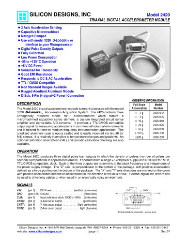
ORDERING INFORMATION
Full Scale
Acceleration
Model
Number
± 2 g 2012-002
± 5 g 2012-005
± 10 g 2012-010
± 25 g 2012-025
± 50 g 2012-050
±100 g 2012-100
±200 g 2012-200
±400 g 2012-400
APPLICATIONS
VIBRATION MONITORING
VIBRATION ANALYSIS
MACHINE CONTROL
MODAL ANALYSIS
ROBOTICS
CRASH TESTING
INSTRUMENTATION
ROTATING MACHINERY
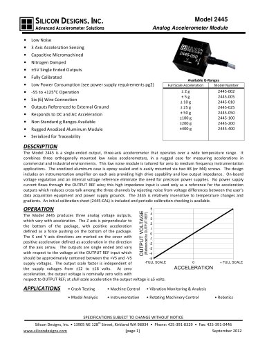
SILICON DESIGNS, INC Model 2012
ANALOG ACCELEROMETER MODULE
! Capacitive Micromachined
! Nitrogen Damped
! ±4V Differential Output or
0.5V to 4.5V Single Ended Output
! Fully Calibrated
! Low Power Consumption
! -55 to +125EC Operation
! +5V DC Power
! Simple, Four Wire Connection
! Serialized for Traceability
! Responds to DC & AC Acceleration
! Non Standard Ranges Available
! Rugged Black Anodized Aluminum Module
DESCRIPTION
The Model 2012 accelerometer module provides a rugged protective case around
an integrated model 1210L accelerometer for measuring accelerations in
commercial/industrial environments. It is tailored for zero to medium frequency
instrumentation applications. The anodized aluminum case is epoxy sealed and
is easily mounted via two #4 (or M3) screws. It is relatively insensitive to
temperature changes and gradients. The cable’s shield is electrically connected
to the case while the ground (GND) wire is isolated from the case. An optional initial
calibration sheet (2012-CAL) and periodic calibration checking are also available.
Please refer to the Model 2210 for applications that require a lower output
impedance or greater power supply rejection ratio than the Model 2012 provides.
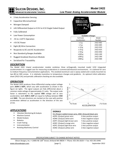
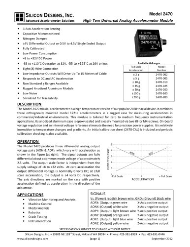
OPERATION
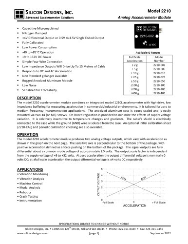
The Model 2012 accelerometer module produces two
analog voltage outputs, AOP & AON, which vary with
acceleration as shown in the graph at right. The signal
outputs are fully differential about a common mode
voltage of ½ VDD (approximately 2.5 volts). At zero
acceleration, the output differential voltage is nominally
zero volts; at +full scale acceleration, the output
differential voltage is +4 volts; at -full scale acceleration
the output differential voltage is -4 volts. The sensitive
axis is perpendicular to the bottom of the package, with
positive acceleration defined as a force pushing on the
bottom of the package.
SIGNAL DESCRIPTIONS
VDD and GND (Power): Red and Black wires respectively. Power (+5 Volts DC)
and ground.
AOP and AON (Output): Green & white wires respectively. AOP voltage
increases (AON decreases) with positive acceleration. At zero acceleration,
both outputs are nominally equal to 2.5 volts. The device experiences positive
(+1g) acceleration with its lid facing up in the Earth’s gravitational field. Either
output can be used individually or the pair can be used differentially.