عضویت
عضویت  ورود اعضا
 راهنمای خرید


Responce Detector RD-80S0 pages
Specification
■ RD-80S Specification
■ RF-8010 software
Optical system
Objective lens
Eyepiece lens
Photo detector
Input
Digital data of analog signal acquired from NI DAQ(Data Acquisition) card
f=82mm F2.5
Number of port
1
View field 5°,
Measurement function Response time & Flicker level of display
Diopter adjustment range:±5 diopter
Measurement mode
Single or Continious
Photomultiplier tube
Output format
Graphic & Text on display
Measurement angle
2°
Measurement distance
Response Detector
R
350mm to ∞ (from front of the objective lens)
Report format
Measurement distance(m)
Measurement area
0. 54
0. 46
0. 74
0. 94
1. 94
4. 94
9. 94
9. 7
Diameter (mmφ)
12. 6
19. 7
26. 7
60. 9
165
350
*These values are slightly changed according to the processing accuracy of aperture mirror.
*The measuring distance is the distance from the mounting hole (at the objective lens side) of the instrument.
Approx. 0.1 – 10,000cd/m2 (for standard illuminant A)
Range
Analog output Analog output 100mV
Analog output 300mV
1
0.1
1
3.3
2
0.33
3.3
1
10
30
4
3.3
33
100
5
10
100
300
6
33
330
1000
7
100
1000
3000
8
330
3300
10000
The values in the above table are the luminance [cd/m2] of the light A
Analog output
■ Standard component
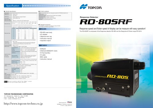
The RD-80SRF is composed of the Response detector RD-80S
and the Response & Flicker scope RF-8010.
Response speed and flicker speed of display can be measure with easy operation!
●RD-80S
10
3
Measurement rage
Microsoft Excel
80μs or less
response speed
*"Analog output response speed" means the time required for the analog output
of this instrument to be changed from 10% of its peak to 90% when observing
the LED driven to the function generator through square waves.
Analog output voltage range
Approx. 0 to 3V
Range to be set
8 ranges (Auto range or manual range)
The RD-80SRF is composed of the Response detector RD-80S and the Response & Flicker scope RF-8010.
・RD-80S main body
・AC adapter
・Objective lens cap
・Instruction manual
・Inspection report
Over/Under Range adjustment function
It is possible to adjust the voltage level for "Over/Under Range" optionally.
Over Range
Approx. 1.5 ~ 3.4V,2.7V (factory setting default)
Under Range
Approx. 0 ~ 1.5V,0.1V (factory setting default)
Photomultiplier tube sensitivity adjustment function It is possible to adjust the photomultiplier tube sensitivity optionally.
Adjustable range
Approx. 0 ~ 1.0V
Approx. 0.2 ~ 0.5V
Adjustment volumes
at the side of
Recommended
this instrument
adjustment range
Adjusts the impressing voltage under the following
conditions. Conditions:When the light 100cd/m2
(Light source A) enters in Range 5
Analog output :1.0V ± 0.05V
*As the sensitivity rises, the noise level also rises. Please use the instrument in the recommended range.
●RF-8010
・Software
・DAQCard-6062E(PC Card)
・IO Terminal Box
・IO cable
・BNC cable
・Instruction manual
Analog output offset adjustment function It is possible to adjust the analog output offset.
Adjustment range
Approx. ±0.5V
Setting at shipment
"Dark" ± 0.5V
Calibration standard
TOPCON calibration standard (Standard light A/23°C ± 3°C/65%RH or less)
Display
Dot matrix LC display (20 characters × 4 lines) with lighting
RS-232C: Protocol is fixed as shown below.
Communication speed
38,400BPS
Data length
7 bits
Parity
Odd
Stop bit
Interface
1 bit
Power
DC12V is supplied by the dedicated AC adapter. AC100V ~ 240V 50/60Hz
Power consumption
Approx. 30W
Operation conditions
Temperature: 20°C ± 50°C Humidity: 50% ± 10%RH or less
Storing conditions
Temperature: -10°C ~ 50°C Humidity: 65%RH or less
External dimensions
Approx. 328.5 (L) × 147.8 (W) × 171.5 (H)
Note
Make sure to carefully read the "User's Manual" to ensure
that you use the product properly and safely.
75-1 Hasunuma-cho, Itabashi-ku, Tokyo 174-8580
Phone: 03-3558-2666
Fax: 03-3558-4661
E-mail: techno-info@topcon.co.jp
Printed using soy ink.
Topcon Technohouse Corporation
2007
Printed in Japan 2008 03 E