عضویت
عضویت  ورود اعضا
 راهنمای خرید


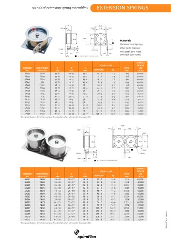
MOTOR SPRINGS0 pages

factors affecting design
MOTOR SPRINGS
RECOMMENDED DISTANCE BETWEEN DRUM FLANGES
EQUALS SPRINGS WIDTH (W)+1mm to 3mm
C MIN
TORQUE OUTPUT
DRUM
SEE DETAILS OF
SPRING ENDS
W
STORAGE DRUM
D3
T
SYMBOLS
C MIN
W = Spring material width
MAY BE INCREASED
T = Spring material thickness
L = Spring length (reference only)
C = Distance between drum centres (min)
D2 = Storage drum diameter
D3 = Torque drum diameter
D1 = Outside diameter of spring when fully wound on storage drum
D4 = Outside diameter of spring when fully wound on torque drum
D3
D2
D2
D4
D1
uses and misuses of Spiroflex springs in our brochure and
web site and refer to Spiroflex if in doubt.
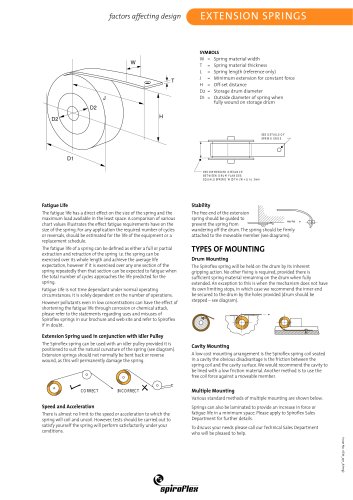
Fatigue Life
The fatigue life has a direct effect on the size of the spring
and the maximum torque output available in the least
space. A comparison of various chart values illustrates the
effect fatigue requirements have on the size of the spring.
For any application the required number of cycles or
reversals should be estimated for the life of the equipment
or a replacement schedule.
Mounting Details
The fatigue life of a spring can be defined as either a full or
partial extraction and retraction of the spring i.e. the spring
can be exercised over its whole length and achieve the
average life expectation, however if it is exercised over any
one section of the spring repeatedly then that section can
be expected to fatigue when the total number of cycles
approaches the life predicted for the spring.
Fatigue Life is not time dependant under normal operating
circumstances; it is solely dependent on the number of
operations.
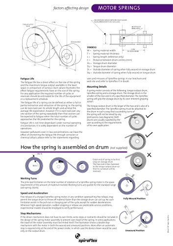
A spring motor consists of the following, torque output drum,
Spiroflex spring and a storage drum. The storage drum is the
smaller of the two and is of a specified diameter. The Spiroflex
spring will grip the storage drum by its own inherent gripping
action.
The torque output drum is the larger of the two and is also of a
specified diameter. The Spiroflex spring must be attached to
the drum in such a way that succeeding turns of
the spring will not be raised by any
protrusions, (see diagrams). Both
drums are usually supplied by the
user according to the requirements
of his own application.
However pollutants even in low concentrations can have the
effect of shortening the fatigue life through corrosion or
chemical attack, please refer to the statements regarding
How the spring is assembled on drum (not supplied)
END B
A
END A
B
Outer end of spring to be first
wrap on storage drum.
The free end is then fastened
to the torque output drum so
that its curvature will be
reversed.
Working Turns
The principal limitation on the total number of rotations of a Spiroflex spring motor is the space
requirement of the amount of material involved. Working turns are quoted for the standard range
(see spring charts).
Speed and Acceleration
Free release of a charged Spiroflex spring motor, or any condition approaching free release, may
permit the torque drum to throw off material faster than the storage drum can coil up. No such
limitation exists in the pull-out or charging part of the cycle, except for sudden decelerations.
Wherever high-speed operation, sudden stopping or release are predictable service conditions,
experimental models should be employed to verify performance.
Fully Wound Position
Stop Mechanisms
Unwound Position
Issue No. 1 (Mtr_spr_A/eng)
If the driven mechanism does not have its own limits, some stops or restraints should be included in
the design of the spring motor assembly to prevent over-travel of the spring. In some applications
the travel of the motor assembly must be limited itself. The illustration shows a double stop
mechanism with the motor in both the wound and unwound positions. More often an automatic
stop is required only at the end of the power stroke, in which case the device shown would be used
only on the output drum.