عضویت
عضویت  ورود اعضا
 راهنمای خرید


PROFIBUS-Interface 16 x digital out0 pages
tr.row {}
td.cell {}
div.block {}
div.paragraph {}
.font0 { font:4.00pt "Arial", sans-serif; }
.font1 { font:5.60pt "Arial", sans-serif; }
.font2 { font:6.00pt "Arial", sans-serif; }
.font3 { font:8.00pt "Arial", sans-serif; }
.font4 { font:10.00pt "Arial", sans-serif; }
.font5 { font:11.00pt "Arial", sans-serif; }
.font6 { font:7.00pt "Impact", sans-serif; }
.font7 { font:9.00pt "Lucida Sans Unicode", sans-serif; }
.font8 { font:13.00pt "Lucida Sans Unicode", sans-serif; }
PROFIBUS-interfaceia x digital out
■ Electrical data
Supply voltage (L+, L-)
DC 20 V to DC 30 V
Power consumption
P = 1.5 W
Galvanic isolation
power supply//bus//electronic//outputs
Bus interface
RS485 with screw-clamping terminals
Display
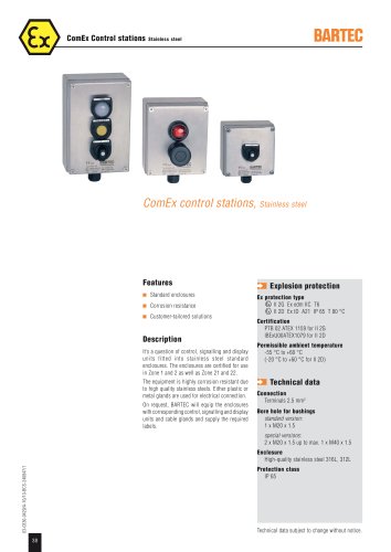
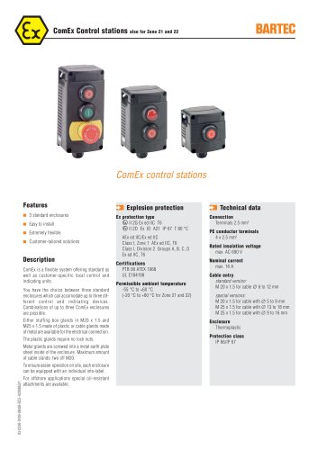
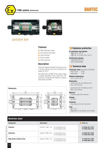
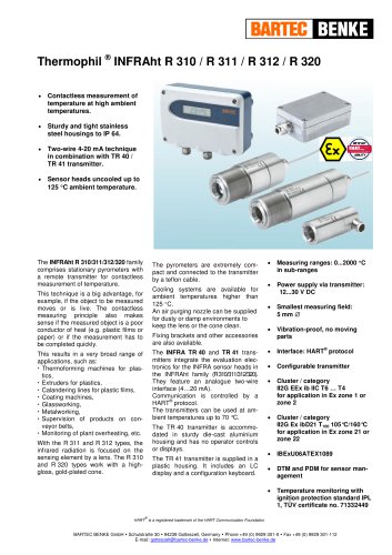
Description
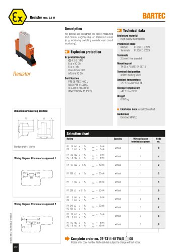
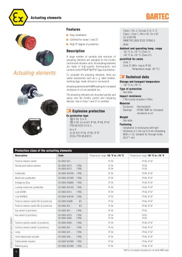
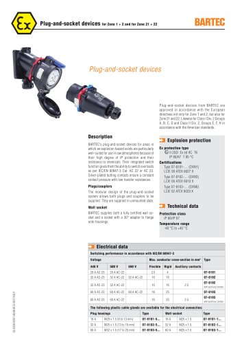
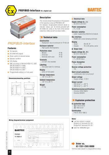
This module allows the activation of 16 actuators in the hazardous area via PROFIBUS-DP. For example, encapsulated solenoid valves or indicator lamps can be directly activated with 24 V/500 mA. LEDs on the front of the module output bus status as well as output states.
ZM Technical data
Construction
Flameproof, clip-on enclosure for TH 35 rail
Enclosure material
High-quality thermoplastics
Protection class
Module IP 66
Terminals IP 20
Terminals with cover IP 30
Terminals
2.5 mm2, fine stranded
Labelling
front panel label for markings
Display
LEDs on front panel
Storage temperature
-40 °C to +60 °C
Ambient temperature
-20 °C to +60 °C
rnUriDUO-illLci Iduc Features
■ 16 channels
■ 24 V/500 mA outputs
■ Direct control of solenoid valves
■ Galvanic isolation
■ LED display
■ EMC according to DIN EN 61000-4-2: 2001, DIN EN 61000-4-3: 2008,
DIN EN 61000-4-4: 2003,
DIN EN 61000-4-6: 2007
■ Programmable address on front panel
Status Outputs
ON, BF, SF
16 x LED yellow, active
■ Output data
Supply voltage (U+, U-)
DC 24 V (18 to 30 V)
Power consumption
P = 240 W (max.)
Power dissipation
P = 7 3 W
Reverse voltage protection
Yes
Short-circuit protection
conditionally short-circuit-proof
Output voltage
Supply voltage - 0.18 V
Output current
500 mA at Ty = +40 °C 400 mA at Ty = +60 °C
Guidelines/norms/certifications
Directive 2004/108/EC
Directive 94/9/EC
Weight
2.1 kg
ZM Explosion protection
Ex protection type
<g> II 2G Ex de IIC <g> I M2 Ex de I
Certification
PTB 97 ATEX 1066 U
Wiring diagram/terminal assignment
13 14 15 16 17 18 19 20 21 22 23 24
Notes
■ Last bus module in system: Bridge A-AX (terminals 30, 33) Bridge B-BX (terminals 29, 32)
■ GSD-file: BARX2901.gsd
16 x Digital out
ADDRESS
ON BF SF
16 15 14
13
^ Order no.
07-7331-2301/0000
Technical data subject to change without notice.
25 26 27 28 29 30 32 33
U- U+ PA PA L- L+
90