عضویت
عضویت  ورود اعضا
 راهنمای خرید


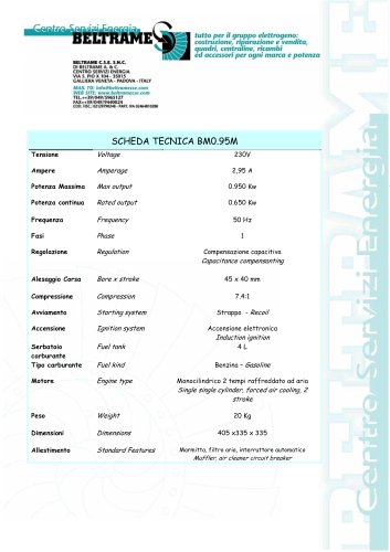
AVR S1550 pages
Sistema Qualità Certificato
BELTRAME CSE, TEL. 049/5965127 - FAX 049/9440024 - MAIL TO: info@beltramecse.com
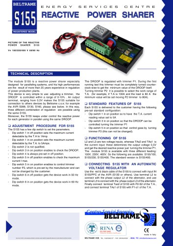
PICTURE OF THE REACTIVE
POWER SHARER S155
Vn 100/220/400 V 50/60 Hz
TECHNICAL DESCRIPTION
THE FACTORY CAN MAKE MODIFICATIONS AND IMPROVEMENTS WITHOUT ANY PRIOR NOTIFICATION
REGISTERED MODEL
The module S155 is a reactive power sharer especially
designed for paralleling systems, and his high performances
are the result of more than 25 years experience in regulation
of power production plants.
This device is very simple to use: adjusting a trimmer, the
DROOP is controlled within a range of 0-10% . An output
terminal, ranging from 0,5V makes the S155 suitable for
connection to others devices by Beltrame c.s.e; for example
the AVR S099, S130, S160, please see below. In this way,
three different combination of regulation are possible using
the same S155.
Moreover, the S155 keeps under control the reactive power
for each generator in parallel using the same DROOP.
ADJUSTMENT PROCEDURE FOR S155
The S155 has a few dip switch to set the parameters.
- Dip switch 1 in off position sets the maximum current
detectable by the T.A to 1Amp.
- Dip switch 1 in on position sets the maximum current
detectable by the T.A. to 5Amps.
- Dip switch 2 is not qualified.
- Dip switch 3 in on position enables to check the DROOP.
- Dip switch 4 is always pre-set in off position.
- Dip switch 5 in off position enables to check the maximum
current I max.
- Dip switch 5 in on position enables to control trimmer
number P3, which is pre-set by the manufacturer and can
not be changed by the customer.
- Dip switch 6 in off position gets the device work in 50 Hz
mode.
- Dip switch 6 in on position gets the device work in 60 Hz
mode.
The DROOP is regulated with trimmer P1. During the first
running test this trimmer must be completely turned counterclock-
wise to get the minimum value of the DROOP itself.
Turning trimmer P2 it is possible to select the work range of
T.A. (for example, if T.A is 100A and the load is 80 A the
minimum value will be set moving P2 trimmer to 80A).
STANDARD FEATURES OF S155
Each S155 is delivered to the customer having the following
pre-set standard configuration:
- Dip switch 1 in on position so to have the T.A. current
reading value set to 5A
- Dip switch 3 in on position so that the DROOP can be
controlled turning the trimmer P1
- Dip switch 5 in on position so that control goes by turning
trimmer P3 (this can not be changed).
FUNCTIONING OF S155
L2 and L3 are two voltage inputs, whereas TAs2 and TAs1 is
the current input; these determines the output voltage 0¸5V
and get the desired reactive power just turning the trimmer P1.
The module S155 is available with three different feeding:
100V, 230V, 400V. So the following are available: S155/100,
S155/230, S155/400. The standard version is S155/400.
CONNECTING S155 WITH AN AUTOMATIC
VOLTAGE REGULATOR
Use the red & black cable of the S155 to connect with input IN
S155/PFC of the AVR (S130 or others). Use terminal L2 to
connect with the phase output L2 of the alternator, and use
terminal L3 to connect with the phase output L3 of the alternator.
Finally connect terminal Tas2 of S155 with P2-S2 of the T.A.,
and connect terminal TAs1 of S155 with P1-s1 of the T.A.
made in Italy