عضویت
عضویت  ورود اعضا
 راهنمای خرید


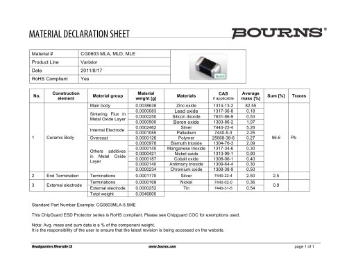
Standard Thick Film Networks 4100R Series0 pages
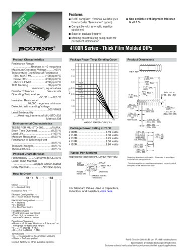
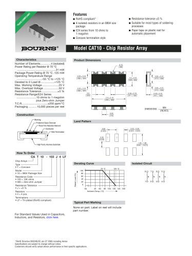
4100R Series - Thick Film Molded DIPs
Specifications are subject to change without notice.
Customers should verify actual device performance in their specific applications.
WATTS
AMBIENT TEMPERATURE ( ° C )
0 70 125
4.00
3.50
3.00
2.50
2.00
1.50
1.00
.50
25
G CU
4108R
4114R
4116R
4118R
4120R
PIN #1 REF.
4.57 + .12/ - .28
(.180 + .005/ - .007)
3.43 + .38/ - .25.
(135 + .015/ - .010)
MAX.
2.03 ± .12
(.080 ± .005)
2.54 ± .25
(.100 ± .010*)
.438 ± .050
(.019 ± .002)
1.65 + .12/ - .07
(.065 + .005/ - .003)
7.87 ± .25
(.310 ± .010)
TO OUTSIDE
WHEN PINS
ARE PARALLEL
6.71 ± .10
(.260 + .005)
(.260 - .000)
8.64 ± .50
(.340 ± .020)
.254 ± .050
(.010 ± .002)
Governing dimensions are in metric. Dimensions in parentheses
are inches and are approximate.
*Terminal centerline to centerline measurements made at point of
emergence of the lead from the body.
27.05
(1.065)
24.51 MAX.
(.965)
21.97 MAX.
(.865)
19.43 MAX.
(.765)
11.81 MAX.
(.465)
8.40 MAX.
TYP. (.331)
.89 ± .25
(.035 ± .010)
TYP.
NON-ACCUM.
TYP.
PART
NUMBER
4114R-1-
152
YYWW
CIRCUIT
RESISTANCE
CODE
PIN ONE
INDICATOR
MANUFACTURER'S
TRADEMARK
DATE CODE
Typical Part Marking
Represents total content. Layout may vary.
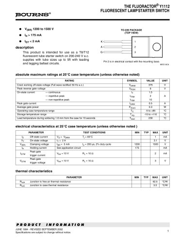
Product Characteristics
Resistance Range
......................10 ohms to 10 megohms
Maximum Operating Voltage..........100 V
Temperature Coefficient of Resistance
50 Ù to 2.2 MÙ................±100 ppm/°C
below 50 Ù ......................±250 ppm/°C
above 2.2 MÙ..................±250 ppm/°C
TCR Tracking .........................50 ppm/°C
maximum; equal values
Resistor Tolerance ................See circuits
Operating Temperature
.................................-55 °C to +125 °C
Insulation Resistance
..................10,000 megohms minimum
Dielectric Withstanding Voltage
.............................................200 VRMS
Lead Solderability
.....Meet requirements of MIL-STD-202
Method 208
Environmental Characteristics
TESTS PER MIL-STD-202.........ÄR MAX.
Short Time Overload..................±0.25 %
Load Life ....................................±1.00 %
Moisture Resistance ..................±0.50 %
Resistance to Soldering Heat
................................................±0.25 %
Terminal Strength.......................±0.25 %
Thermal Shock...........................±0.25 %
Physical Characteristics
Flammability .........Conforms to UL94V-0
Lead Frame Material
..........................Copper, solder coated
Body Material ..................Novolac epoxy
Package Power Rating at 70 °C
4108R......................................1.69 watts
4114R......................................2.00 watts
4116R......................................2.25 watts
4118R......................................2.50 watts
4120R......................................2.80 watts
How To Order
41 14 R - 1 - 152 __ __
Model
(41 = Molded DIP)
Number of Pins
Physical Configuration
(R = Thick Film Low Profile)
Electrical Configuration
• 1 = Isolated
• 2 = Bussed
• 3 = Dual Terminator
Resistance Code
• First 2 digits are significant
• Third digit represents the
number of zeros to follow.
Resistance Tolerance
• Blank = ±2 % (see “Resistance Tolerance” on
next page for resistance range)
• F = ±1 % (100 Ù - 1 MÙ)
• D = ±0.5 % (100 Ù - 1 MÙ)
Terminations
• LF = Tin-plated (RoHS compliant version)
• Blank = Tin/Lead-plated
Consult factory for other available options.
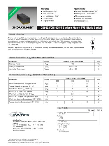
Features
¡ RoHS compliant* versions available (see
How to Order “Termination” option)
¡ Compatible with automatic insertion
equipment
¡ Superior package integrity
¡ Marking on contrasting background for
permanent identification
¡ Now available with improved tolerance
to ±0.5 %
Package Power Temp. Derating Curve Product Dimensions
*RoHS COMPLIANT
VERSIONS
AVAILABLE
*RoHS Directive 2002/95/EC Jan 27 2003 including Annex
For Standard Values Used in Capacitors,
Inductors, and Resistors, click here.