عضویت
عضویت  ورود اعضا
 راهنمای خرید


PRISMIC A120 pages

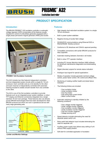
PRISMIC® A12
Excitation System
PRODUCT SPECIFICATION
Introduction
Features
The PRISMIC® A12 excitation system has been designed to
control the excitation of a brushless generator. It incorporates
the latest digital micro controller technology to make it the most
comprehensive and compact controller available.
•t
•t
•t
•t
•t
•t
•t
•t
•t
•t
•t
•t
•t
•t
•t
•t
•t
•t
•t
The PRISMIC® A12 is based upon proven technology and
combines the experience and hardware of the BRUSH
PRISMIC® A50 excitation controller. It includes, additional
features such as intergrated speed detection, power system
stabiliser and sychronisation.
The PRISMIC® A12 is produced on a plate mounted system
either as a single channel or twin channel arrangement. As a
twin system each controller acts as a hot standby for the other
and is independently controlled with auto tracking, and smooth
transfer. An optional colour display screen is also available.
Complete excitation system mounted on a plate
Available either as a single unit or as a high integrity twin
configuration
Integrated Power System Stabiliser (optional)
Integrated auto synchroniser (optional)
Integrated speed detection eliminating need for seperate
speed switch
Rotor earth fault detector input included eliminating the
need for separate unit
Negative forcing of exciter field voltage
Modes of operation include generator terminal voltage
control, power factor control, VAr control and offload VArs
Digital Outputs
Analogue Input Signal for special application
Auxiliary power supply input allows easy setting of unit
without PMG supply present
Manual Reference
Soft start for controlled application of excitation
Diode Failure Detection and Indication
HMI (Human Machine Interface) software for advanced
maintenance diagnostics and downloading of data
Oscilloscope style trending and analogue data logging
(5ms resolution) via HMI
Event Logging
Externally mounted display interface computer (Optional)
Automatic and manual excitation limiters
The following limiters are included:
•t
•t
•t
•t
•t
•t
Under Excitation Limiter
Over Excitation Limiter
Over Flux (V/Hz) Limiter
Stator Current Limiter
Fast Acting Field Current Limiter
Terminal Voltage Limiter
Automatic transfer of control to hot standby channel initiated by:t
•t
•t
•t
•t
•t
•t
Over Voltage Monitor Triggered
Under Voltage Monitor Triggered
Over Excitation Monitor Triggered
Under Excitation Monitor Triggered
Over Flux Monitor Triggered
Voltage Sensing Error
The PRISMIC® A12 includes the following communication port
•t
•t
•t
•t
Limiter and Monitor Settings
•t
1 x RS232 service port
1 x CANbus port for communication with hot standby tt
unit in twin configurations
1 x CANbus port available for connection of display
t
interface computer
1 x RS485 / RS232 Modbus RTU port for SCADA/tt
DCS communications
1 x PROFIBUS port (optional)