عضویت
عضویت  ورود اعضا
 راهنمای خرید


PRISMIC A300 pages
PRISMIC® A30
Excitation Controller
PRODUCT SPECIFICATION
Introduction
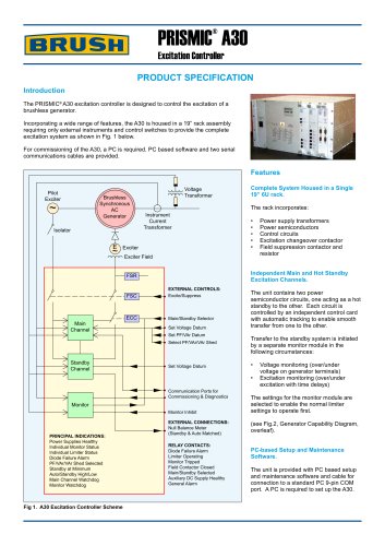
The PRISMIC® A30 excitation controller is designed to control the excitation of a
brushless generator.
Incorporating a wide range of features, the A30 is housed in a 19” rack assembly
requiring only external instruments and control switches to provide the complete
excitation system as shown in Fig. 1 below.
For commissioning of the A30, a PC is required. PC based software and two serial
communications cables are provided.
Features
Pilot
Exciter
Brushless
Synchronous
AC
Generator
~
Isolator
E
~
Voltage
Transformer
The rack incorporates:
Instrument
Current
Transformer
Exciter
Exciter Field
FSC
EXTERNAL CONTROLS:
Excite/Suppress
ECC
Main/Standby Selector
Set Voltage Datum
Set PF/VAr Datum
Select PF/VAr/VAr Shed
Standby
Channel
•t
•t
•t
•t
•t
t
Power supply transformers
Power semiconductors
Control circuits
Excitation changeover contactor
Field suppression contactor and t
resistor
Independent Main and Hot Standby
Excitation Channels.
FSR
Main
Channel
Complete System Housed in a Single
19” 6U rack.
Set Voltage Datum
Communication Ports for
Commissioning & Diagnostics
The unit contains two power
semiconductor circuits, one acting as a hot
standby to the other. Each circuit is t
controlled by an independent control card
with automatic tracking to enable smooth
transfer from one to the other.
Transfer to the standby system is initiated
by a separate monitor module in the
following circumstances:
•t
t
•t
t
Voltage monitoring (over/under t t
voltage on generator terminals)
Excitation monitoring (over/under t
excitation with time delays)
Monitor Inhibit
The settings for the monitor module are
selected to enable the normal limiter
settings to operate first.
EXTERNAL CONNECTIONS:
Null Balance Meter
(Standby & Auto Matched)
(see Fig.2, Generator Capability Diagram,
overleaf).
Monitor
PRINCIPAL INDICATIONS:
Power Supplies Healthy
Individual Monitor Status
Individual Limiter Status
Diode Failure Alarm
PF/VAr/VAr Shed Selected
Standby at Minimum
Auto/Standby High/Low
Main Channel Watchdog
Monitor Watchdog
Fig 1. A30 Excitation Controller Scheme
RELAY CONTACTS:
Diode Failure Alarm
Limiter Operating
Monitor Tripped
Field Contactor Closed
Main/Standby Selected
Auxiliary DC Supply Healthy
General Alarm
PC-based Setup and Maintenance
Software.
The unit is provided with PC based setup
and maintenance software and cable for
connection to a standard PC 9-pin COM
port. A PC is required to set up the A30.