عضویت
عضویت  ورود اعضا
 راهنمای خرید


Static and Dynamic Analysis of Concrete Turbine Foundations0 pages
Static and Dynamic Analysis of Concrete Turbine
nnnnFoundations
nnnnPeter Nawrotzki, Dr-Ing., Managing Director, GERB Engineering GmbH, Essen, Germany; Giinter Hiiffmann, Dr-Ing., Senior
nnnnAdviser, GERB Vibration Control Systems, Berlin, Germany and Timur Uzunoglu, Dr-Ing., Managing Director, convex ZT GmbH,
nnnnGraz, Austria
nnnnSummary
nnnnThe paper presents a systematic overview of the static and dynamic analysis of
nnnnturbine foundations made of reinforced concrete. It discusses the load cases to
nnnnbe applied, the required ultimate limit and serviceability limit state checks, the
nnnnassessment of the static and dynamic foundation stiffness and special provisions
nnnnrequired in seismic areas. Turbine foundation design is an ambitious task, requir-
nnnning attention to detail and plausibility checking of all input/output parameters, as
nnnna shut down of a turbine caused by an insufficiently designed and built founda-
nnnntion will lead to damage that is in no proportion to its cost.
nnnnKeywords: turbine foundation; block foundation; table foundation; spring
nnnnsupport; structural dynamics; vibration amplitude; vibration velocity; misalign-
nnnnment matrix.
nnnnIntroduction
nnnnDuring the first half of the twentieth
nnnncentury, engineering of turbine foun-
nnnndations was limited to a static analysis
nnnnbased on dead loads plus an additional,
nnnnarbitrary vibration charge amounting
nnnnto 3 to 5 times of the machine weight
nnnnacting as a vertical, equivalent static
nnnnload.
nnnnIn 1955, the publication of the first edi-
nnnntion of DIN 4024 provided for the first
nnnntime rules for a standardised static and
nnnndynamic analysis. Although it was ob-
nnnnvious that the calculation of the first
nnnnorder natural frequency alone was not
nnnnsufficient to characterise the dynamic
nnnnbehaviour of turbine foundations, it
nnnnneeded the development of computers
nnnnto allow models and methods for the
nnnnanalysis of turbine foundations to pro-
nnnnvide a more precise assessment of the
nnnndynamic behaviour.
nnnnturbine leading to a table-type foun-
nnnndation (Fig. 2), with two possible ar-
nnnnrangements: either, the condenser is
nnnnwelded to the LP turbine nozzle with
nnnna smaller part of the condenser weight
nnnn^^^^^^
nnnn^A^A^A^A^AAAA
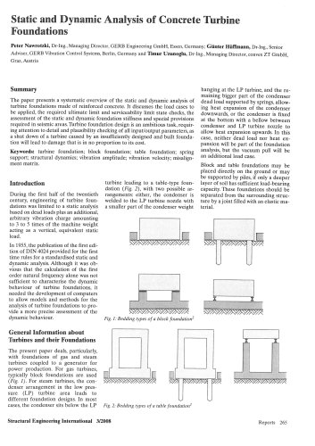
nnnnFig. 1: Bedding types of a block foundation2
nnnnhanging at the LP turbine, and the re-
nnnnmaining bigger part of the condenser
nnnndead load supported by springs, allow-
nnnning heat expansion of the condenser
nnnndownwards, or the condenser is fixed
nnnnat the bottom with a bellow between
nnnncondenser and LP turbine nozzle to
nnnnallow heat expansion upwards. In this
nnnncase, neither dead load nor heat ex-
nnnnpansion will be part of the foundation
nnnnanalysis, but the vacuum pull will be
nnnnan additional load case.
nnnnBlock and table foundations may be
nnnnplaced directly on the ground or may
nnnnbe supported by piles, if only a deeper
nnnnlayer of soil has sufficient load-bearing
nnnncapacity. These foundations should be
nnnnseparated from the surrounding struc-
nnnnture by a joint filled with an elastic ma-
nnnnterial.
nnnnXAAVA>
nnnn^A
nnnnI
nnnn^A^A^A^A^ASAA
nnnnGeneral Information about
nnnnTurbines and their Foundations
nnnnThe present paper deals, particularly,
nnnnwith foundations of gas and steam
nnnnturbines coupled to a generator for
nnnnpower production. For gas turbines,
nnnntypically block foundations are used
nnnn(Fig. 1). For steam turbines, the con-
nnnndenser arrangement in the low pres-
nnnnsure (LP) turbine area leads to
nnnndifferent foundation designs. In most
nnnncases, the condenser sits below the LP
nnnnn
nnnn^^^AAAAA^/A
nnnnL □
nnnn'AAsA/AÏ,
nnnnE
nnnn11
nnnnm$ ^AAAA^A^AA/A
nnnnFig. 2: Bedding types of a table foundation
nnnnStructural Engineering International 3/2008
nnnnReports 265
"