عضویت
عضویت  ورود اعضا
 راهنمای خرید


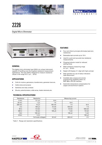
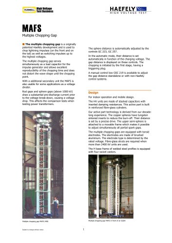
2292 Winding Resistance Meter0 pages
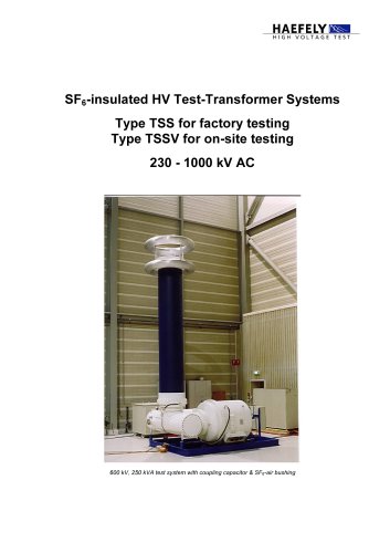
OPTIMISED TOOL FOR THE MEASUREMENT OF WINDING
RESISTANCES ON POWER TRANSFORMERS
Marc Muller1
1Haefely Test AG, Basel, Switzerland
*Email: mueller.marc@haefely.com
Abstract: The topic of this paper is the analysis of the fundamentals of the winding resistance measurement
and their application for the development of an optimized tool. The ultimate goal is to create a portable
device, which measures a complete transformer the fastest and easiest way possible. The influence of the
charging voltage and the measuring current on the measuring time has to be analyzed. Another important
issue is the stabilization time on low ohmic delta windings. Further, testing time can be reduced by
introducing a demagnetization feature, which eliminates the need of applying high voltage AC after a DC
resistance test. Finally, the implementation of the optimized tool is presented with its efficient connection
scheme and the multi-channel architecture.
1 INTRODUCTION
Fast, efficient and accurate measurement of
winding resistances on large power transformers
creates several difficulties.
Long charging and discharging times, unstable
values on closed delta winding systems due to
long stabilization times, inaccurate temperature
measurements for resistance correction, residual
magnetism and its unwanted effects, inefficient
connection and disconnection of the measuring
equipment are just some of the difficulties to deal
with.
The paper describes an integrated, mobile
instrument developed to speed up the stabilisation
time when supplying DC to a transformer winding
by an intelligent magnetic-flux optimised charging.
With example diagrams of various transformers the
charging and stabilisation effects are shown.
After applying DC to a transformer, the core
remains magnetized. This can cause problems for
further measurements or reconnecting the
transformer to the grid. Thus, an integrated, low
voltage demagnetization function to bring a power
transformer into a defined, demagnetised state will
be shown.
Typical problems arising when connecting a
measuring system to a power transformer have
been solved. In particular these problems are time
consumption and faulty connections, which have
been solved by a fully integrated connection set
and a multiplexing circuit. Error possibilities in
setting up the measurement equipment have to be
faced and eliminated by offering state-of-the-art
graphical, self-explanatory user interfaces with
online information about all related values and
conditions in an easy and well-arranged way.
2 SUPPLY VOLTAGE AND CURRENT
2.1 General measuring principle
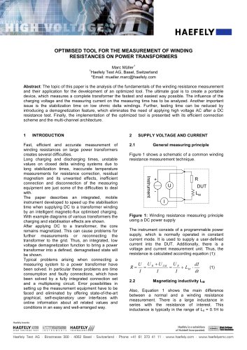
Figure 1 shows a schematic of a common winding
resistance measurement technique.
Figure 1: Winding resistance measuring principle
using a DC power supply
The instrument consists of a programmable power
supply, which is normally operated in constant
current mode. It is used to supply a user-defined
current into the DUT. Additionally, there is a
voltage and current measurement unit. Thus, the
resistance is calculated according equation (1):
(1)
2.2
Magnetizing inductivity LM
Also, Equation 1 shows the main difference
between a normal and a winding resistance
measurement. There is a large inductance in
series with the resistance of interest. This
inductance is typically in the range of L0 = 0.1 H to
Haefely brands
HAEFELYJ&S ILUJUMM HAEFELYJ^W?
HIGH VOLTAGE TEST | » & j ft J M E H T J TCCHHQLCHJV WWW
Haefely Test AG ■ Birsstrasse 300 ■ 4052 Basel ■ Switzerland ■ Phone +41 61 373 41 11 ■ www.haefely.com ■ www.haefelyemc.com
Haefely is a subsidiary High ifoliaga
of Hubbell Incorporated, ---Test Business
"