عضویت
عضویت  ورود اعضا
 راهنمای خرید


Fixed Displacement HV10 and HV20 (Single Pump)0 pages
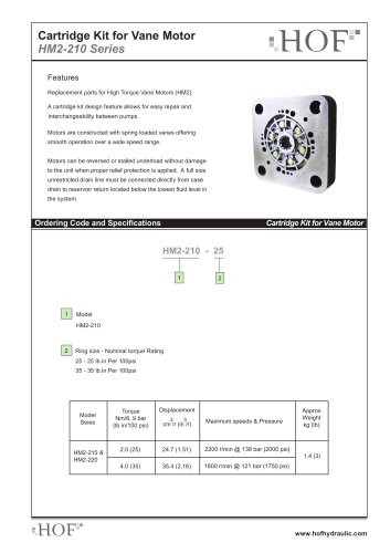
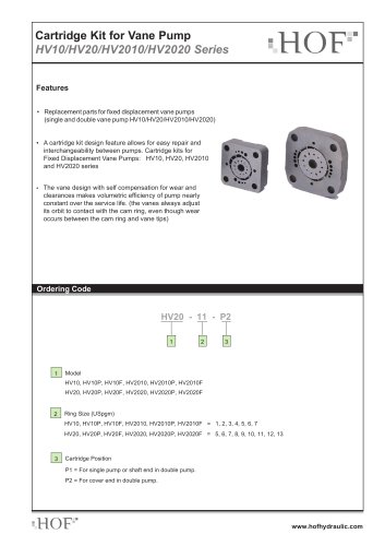
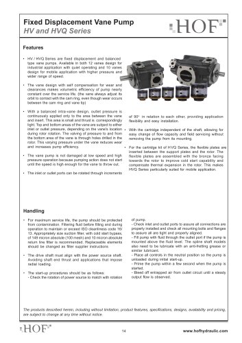
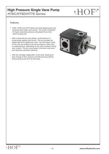
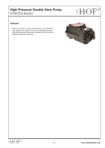
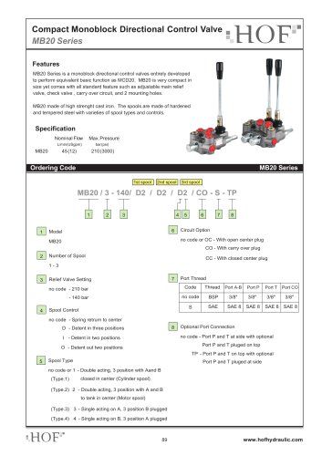
Fixed Displacement Vane Pump
HV10 and HV20 Series
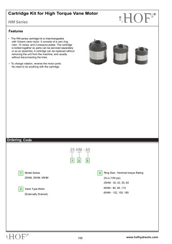
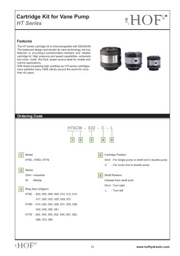
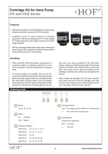
Features
• HV10 / HV20 Series are fixed displacement and balanced • The vane pump is not damaged at low speed and high
pressure operation because pumping action does not start
until the speed is high enough for the vane to throw out.
With hydraulically balanced design, the bearing is externally
loaded only. Therefore, the pump requires minimized
maintenance with long service life.
type vane pumps. With compact sizes, they are available
in single pumps and double pumps for both industrial and
mobile application.
• The vane design with self compensation for wear and
clearances makes volumetric efficiency of pump nearly
constant over the service life. (the vanes always adjust its
orbit to contact with the cam ring, even though wear occurs
between the cam ring and vane tips)
• The inlet or outlet ports can be rotated through increments
of 90o in relation to each other, providing application
flexibility and easy installation.
• With optional flow control and priority valve covers, the pump
can be used in more applications. The flow control cover
can limit the flow to the primary circuit at the required flow
rate, while diverts remaining flow to the tank. The priority
valve cover maintains a constant flow to the primary circuit,
while diverts remaining flow to the secondary circuit. Each
cover comes with a relief valve to limits the maximum
pressure of the primary circuit.
Handling
- Fill pump with fluid through the outlet port if the pump is
mounted above the fluid level. The spline shaft models
also need to be lubricated with an anti-fretting grease or
similar lubricant.
- Place all controls in the neutral position so the pump is
unloaded during initial start-up.
- Prime the pump within a few second when the pump is
started.
- Bleed off entrapped air from outlet circuit until a steady
output flow is observed.
• For maximum service life, the pump should be protected
from contamination. Filtering fluid before filling and during
operation to maintain or exceed ISO cleanliness code 17/
14. Replaceable elements should be changed as filter
supplier instructions
• The drive shaft must align with the power source shaft.
Avoiding shaft end thrust and applications that impose
radial loading.
• The start-up procedures should be as follows:
- Check the rotation of power source to match the rotation
of pump.
- Check inlet and outlet ports to assure all connections are
properly installed and check all mounting bolts and flanges
to assure all are tight and properly aligned.
The products described herein, including without limitation, product features, specifications, designs, availability and pricing,
are subject to change at any time without notice.
1
www.hofhydraulic.com
"