عضویت
عضویت  ورود اعضا
 راهنمای خرید


KEA 101 SPL00 pages
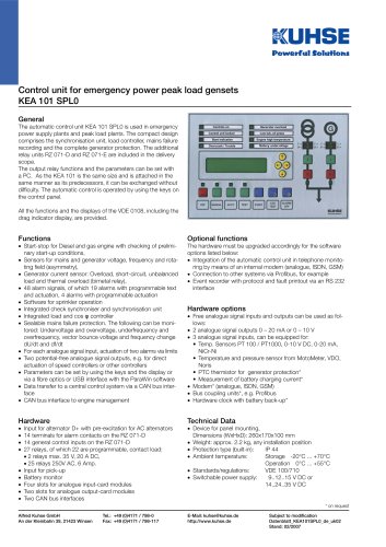
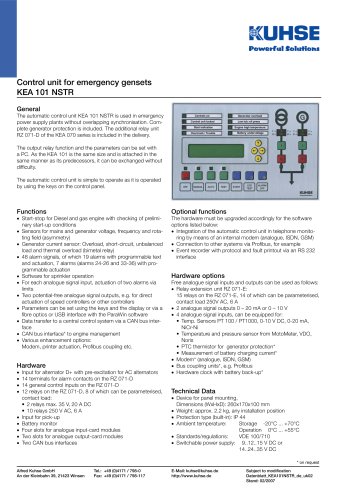
Control unit for emergency power peak load gensets
KEA 101 SPL0
General
The automatic control unit KEA 101 SPL0 is used in emergency
power supply plants and peak load plants. The compact design
comprises the synchronisation unit, load controller, mains failure
recording and the complete generator protection. The additional
relay units RZ 071-D and RZ 071-E are included in the delivery
scope.
The output relay functions and the parameters can be set with
a PC. As the KEA 101 is the same size and is attached in the
same manner as its predecessors, it can be exchanged without
difculty. The automatic control is operated by using the keys on
the control panel.
All the functions and the displays of the VDE 0108, including the
drag indicator display, are provided.
Functions
• Start-stop for Diesel and gas engine with checking of preliminary start-up conditions,
• Sensors for mains and generator voltage, frequency and rotating eld (asymmetry),
• Generator current sensor: Overload, short-circuit, unbalanced
load and thermal overload (bimetal relay),
• 48 alarm signals, of which 19 alarms with programmable text
and actuation, 4 alarms with programmable actuation
• Software for sprinkler operation
• Integrated check synchroniser and synchronisation unit
• Integrated load and cos φ controller
• Sealable mains failure protection. The following can be monitored: Undervoltage and overvoltage, underfrequency and
overfrequency, vector bounce voltage and frequency change
dU/dt and df/dt
• For each analogue signal input, actuation of two alarms via limits
• Two potential-free analogue signal outputs, e.g. for direct
actuation of speed controllers or other controllers
• Parameters can be set by using the keys and the display or
via a bre optics or USB interface with the ParaWin software
• Data transfer to a central control system via a CAN bus interface
• CAN bus interface to engine management
Hardware
•
•
•
•
•
•
•
•
•
Optional functions
The hardware must be upgraded accordingly for the software
options listed below:
• Integration of the automatic control unit in telephone monitoring by means of an internal modem (analogue, ISDN, GSM)
• Connection to other systems via Probus, for example
• Event recorder with protocol and fault printout via an RS 232
interface
Hardware options
• Free analogue signal inputs and outputs can be used as follows:
• 2 analogue signal outputs 0 20 mA or 0 10 V
• 3 analogue signal inputs, can be equipped for:
Temp. Sensors PT 100 / PT1000, 0-10 V DC, 0-20 mA,
NiCr-Ni
Temperature and pressure sensor from MotoMeter, VDO,
Noris
PTC thermistor for generator protection*
Measurement of battery charging current*
• Modem* (analogue, ISDN, GSM)
• Bus coupling units*, e.g. Probus
• Hardware clock with battery back-up*
Technical Data
Input for alternator D+ with pre-excitation for AC alternators
14 terminals for alarm contacts on the RZ 071-D
14 general control inputs on the RZ 071-D
27 relays, of which 22 are programmable, contact load:
• 2 relays max. 35 V, 20 A DC,
• 25 relays 250V AC, 6 Amp.
Input for pick-up
Battery monitor
Four slots for analogue input-card modules
Two slots for analogue output-card modules
Two CAN bus interfaces
• Device for panel mounting,
Dimensions (WxHxD): 260x170x100 mm
• Weight: approx. 2.2 kg, any installation position
• Protection type (built-in):
IP 44
• Ambient temperature:
Storage -20°C ... +70°C
Operation 0°C ... +55°C
• Standards/regulations:
VDE 100/710
• Switchable power supply:
9..12..15 V DC or
14..24..35 V DC
* on request
Alfred Kuhse GmbH
An der Kleinbahn 39, 21423 Winsen
Tel.: +49 (0)4171 / 798-0
Fax: +49 (0)4171 / 798-117
E-Mail: kuhse@kuhse.de
http://www.kuhse.de
Subject to modication
Datenblatt_KEA101SPL0_de_uk02
Stand: 02/2007