عضویت
عضویت  ورود اعضا
 راهنمای خرید


ul TR a -S lim ® Thin-Section Bearings0 pages
Sect i on 2–Selec tio n Tab les
REALI-SLIM® Bearings Catalog 300
©KAYDON® Corporation Issue 10
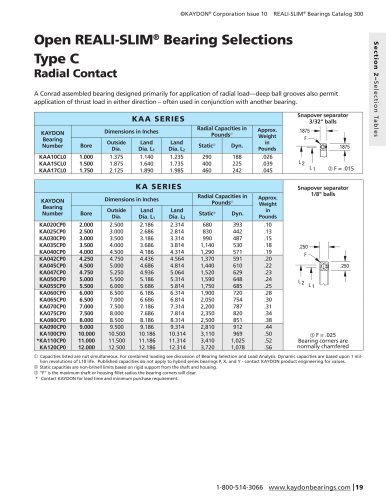
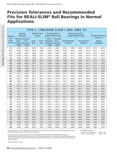
ULTRA-SLIM® Thin-Section Bearings
Ideal for applications in robotics,
inspection equipment, satellites,
cameras… anywhere precise positioning
and lightweight designs are critical.
At just 2.5 mm wide, ULTRA-SLIM® bearings are available
in bore sizes ranging from 35 mm to 170 mm for an array
of applications. Their compact profile allows you to use
ULTRA-SLIM® bearings in many highly confined spaces.
Precision-engineered ULTRA-SLIM® bearings are made of
stainless steel for corrosion resistance. They are available in
angular contact (Type A), radial contact (Type C), and fourpoint contact (Type X) styles. (See selection charts at right.)
Hybrid bearings with ceramic balls are available upon request.
These configurations are used often when lubrication is
marginal or when lower wear generation and/or lower torque
levels are required.
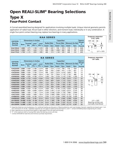
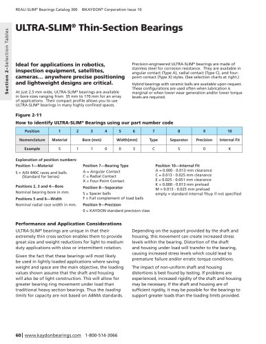
Figure 2-11
How to identify ULTRA-SLIM® Bearings using our part number code
Position
1
Nomenclature
Material
Example
S
2
3
4
Bore (mm)
1
Explanation of position numbers:
Position 1—Material
1
5
6
Width(mm)
0
0
7
8
9
10
Type
Separator
Precision
Internal Fit
C
S
0
K
3
Position 7—Bearing Type
S = AISI 440C races and balls
(Standard for Series)
A = Angular Contact
C = Radial Contact
X = Four-Point Contact
Positions 2, 3 and 4—Bore
Position 8—Separator
Nominal bearing bore in mm.
Positions 5 and 6—Width
S = Spacer balls
F = Full complement of load balls
Nominal radial race width in mm.
Position 10—Internal Fit
A = 0.000 - 0.013 mm clearance
C = 0.013 - 0.025 mm clearance
E = 0.025 - 0.051 mm clearance
K = 0.000 - 0.013 mm preload
M = 0.013 - 0.025 mm preload
empty = tandard internal fitup if not specified
s
Position 9—Precision
0 = KAYDON standard precision class
Performance and Application Considerations
ULTRA-SLIM® bearings are unique in that their
extremely thin cross section enables them to provide
great size and weight reductions for light to medium
duty applications with slow or intermittent rotation.
Given the fact that these bearings will most likely
be used in lightly loaded applications where saving
weight and space are the main objective, the loading
values shown assume that the shaft and housing
will also be of light construction. This will allow for
greater bearing ring movement under load than
traditional heavy section bearings. Thus the loading
limits for capacity are not based on ABMA standards.
60 | www.kaydonbearings.com 1-800-514-3066
Depending on the support provided by the shaft and
housing, this movement can create increased stress
levels within the bearing. Distortion of the shaft
and housing under load will transfer to the bearing,
causing increased stress levels which could lead to
premature failure and/or erratic torque conditions.
The impact of non-uniform shaft and housing
distortions is best found by testing. If problems are
experienced, increased rigidity of the shaft and housing
may be necessary. If the shaft and housing are of
sufficient rigidity, it may be possible for the bearings to
support greater loads than the loading limits provided.