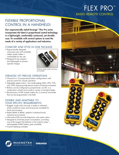
عضویت
عضویت  ورود اعضا
 راهنمای خرید


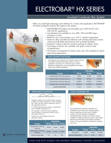
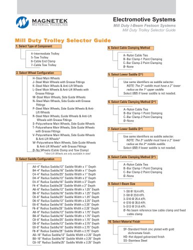
Mill Duty I-Beam Festoon0 pages
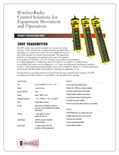
Track Length ■
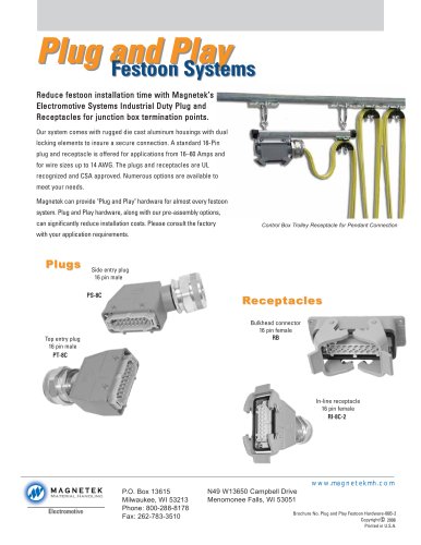
nnnnFestoon Systems
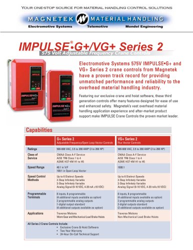
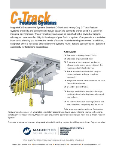
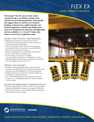
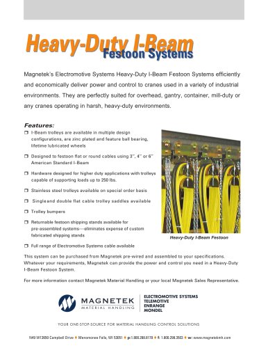
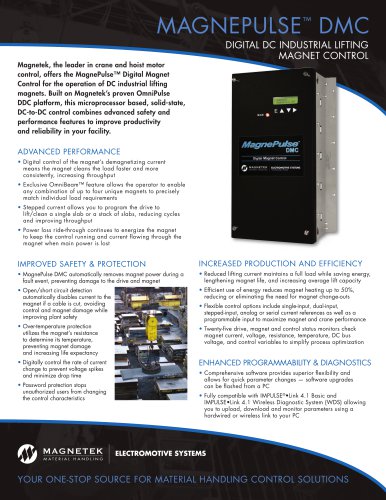
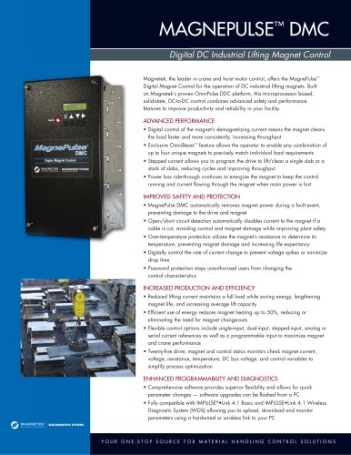
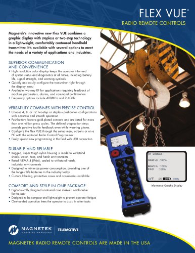
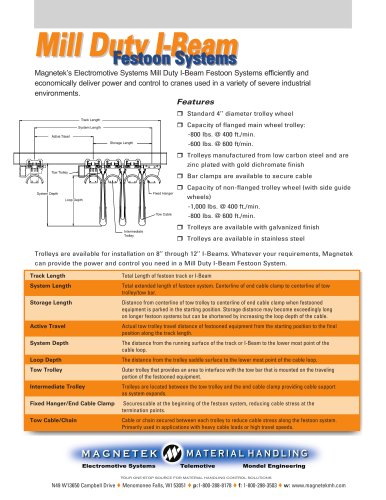
nnnnMagnetek's Electromotive Systems Mill Duty l-Beam Festoon Systems efficiently and
nnnneconomically deliver power and control to cranes used in a variety of severe industrial
nnnnenvironments.
nnnnFeatures
nnnn□ Standard 4" diameter trolley wheel
nnnn□ Capacity of flanged main wheel trolley:
nnnn-800 lbs. @ 400 ft./min.
nnnn-600 lbs. @ 600 ft/min.
nnnn□ Trolleys manufactured from low carbon steel and are
nnnnzinc plated with gold dichromate finish
nnnn□ Bar clamps are available to secure cable
nnnn□ Capacity of non-flanged trolley wheel (with side guide
nnnnwheels)
nnnn-1,000 lbs. @ 400 ft./min.
nnnn-800 lbs. @ 600 ft./min.
nnnn□ Trolleys are available with galvanized finish
nnnn□ Trolleys are available in stainless steel
nnnnTrolleys are available for installation on 8" through 12" l-Beams. Whatever your requirements, Magnetek
nnnncan provide the power and control you need in a Mill Duty l-Beam Festoon System.
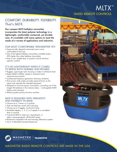
nnnnFixed Hanger
nnnnSi
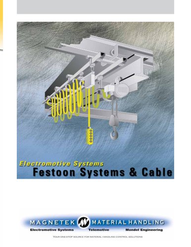
nnnnTrack Length
nnnnSystem Length
nnnnTotal Length of festoon track or l-Beam
nnnnStorage Length
nnnnF
nnnnLoop Dept
nnnnTow Trolley
nnnnIntermediate Trolley
nnnnFixed Hanger/End Cable Clamp
nnnnTow Cable/Chain
nnnnTotal extended length of festoon system. Centerline of end cable clamp to centerline of tow
nnnntrolley/tow bar.
nnnnDistance from centerline of tow trolley to centerline of end cable clamp when festooned
nnnnequipment is parked in the starting position. Storage distance may become exceedingly long
nnnnon longer festoon systems but can be shortened by increasing the loop depth of the cable.
nnnnActual tow trolley travel distance of festooned equipment from the starting position to the final
nnnnposition along the track length.
nnnnThe distance from the running surface of the track or l-Beam to the lower most point of the
nnnncable loop.
nnnnThe distance from the trolley saddle surface to the lower most point of the cable loop.
nnnnOuter trolley that provides an area to interface with the tow bar that is mounted on the traveling
nnnnportion of the festooned equipment.
nnnnTrolleys are located between the tow trolley and the end cable clamp providing cable support
nnnnas system expands.
nnnnSecurescable at the beginning of the festoon system, reducing cable stress at the
nnnntermination points.
nnnnCable or chain secured between each trolley to reduce cable stress along the festoon system.
nnnnPrimarily used in applications with heavy cable loads or high travel speeds.
nnnnAGNETEK
nnnnMATERIAL HANDLING
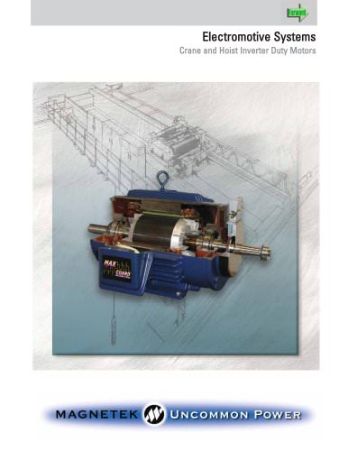
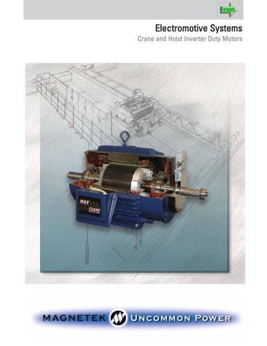
nnnnElectromotive Systems
nnnnTelemotive
nnnnMondei Engineering
nnnnYOUR ONE-STOP SOURCE FOR MATERIAL HANDLING CONTROL SOLUTIONS
nnnnN49W13650 Campbell Drive Menomonee Falls, Wl 53051 p:1-800-288-8178 ♦ f: 1-800-298-3503 w: www.magnetekmh.com
"