عضویت
عضویت  ورود اعضا
 راهنمای خرید


Characterization of Ambient Ion Optics using IonCCD? µ-Array Detector in a Ion Mobility Spectrometer0 pages
Characterization of Ambient Ion Optics using IonCCD™ µ-Array Detector in a Ion Mobility Spectrometer
Stephen
1,
Davila
Omar
2,
Hadjar
Gary
1
Eiceman
1Department
of Chemistry and BioChemistry, New Mexico State University, Las Cruces, New Mexico 88003
2OI Analytical, CMS Field Products, 2148 Pelham Pkwy, Bldg 400, Pelham, AL 35124
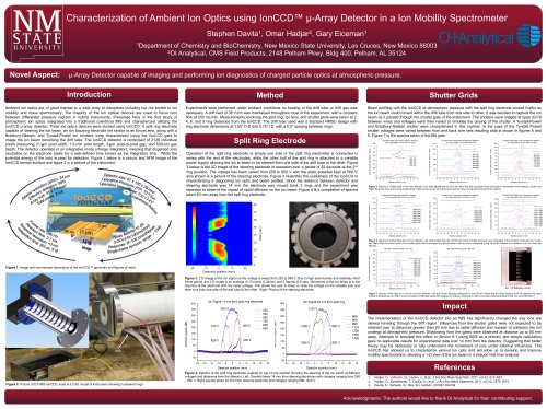
Novel Aspect:
µ-Array Detector capable of imaging and performing ion diagnostics of charged particle optics at atmospheric pressure.
Introduction
Method
Ambient ion optics are of great interest to a wide array of disciplines including but not limited to ion
mobility and mass spectrometry. The majority of the ion optical devices are used to focus ions
between differential pressure regions in hybrid instruments. Presented here is the first study of
atmospheric ion optics integrated into a traditional cylindrical IMS and characterized utilizing the
IonCCD μ-array detector. Three ion optics devices were studied using IonCCD. A split ring electrode
capable of steering the ion beam, an ion focusing electrode set similar to an Einzel lens, along with a
Bradbury-Nilesen, and Tyndall-Powell ion shutters were characterized using the IonCCD gate to
image the ion beam traversing the drift tube. The IonCCD detector is comprised of 2126 individual
pixels measuring 21-μm pixel width, 1.5-mm pixel length, 3-μm pixel-to-pixel gap, and 500-nm gap
depth. The detector operates in an integrative mode (charge integrator), meaning that dispersed ions
neutralize on the electrode pixels for a well-defined time known as the integration time. While the
potential energy of the ions is used for detection. Figure 1 below is a picture and AFM image of the
IonCCD sensor surface and figure 2 is a picture of the instrument.
Shutter Grids
Experiments were performed under ambient conditions no heating of the drift tube or drift gas was
necessary. A drift field of 38 V/cm was maintained throughout most of the experiment, with a constant
flow of 200 mL/min. Measurements involving the split ring, ion lens, and shutter grids were taken at 2,
4, 6, and 8 ring distances from the IonCCD. The drift tube used was a standard NMSU design with
ring electrode dimensions at 1.50” O.D and 0.75” I.D. with a 0.5” spacing between rings.
Beam profiling with the IonCCD at atmospheric pressure with the split ring electrode proved fruitful as
the ion beam could moved within the drift tube from one side to other. It was decided to capture the ion
beam as it passed through the shutter gate of the instrument. The shutters were imaged at open ΔV=0
between wires and voltages were then varied to simulate the closing of the shutter. A Tyndall-Powell
and Bradbury-Nielsen shutter were characterized in this manner. In the case of the Tyndall Powell
shutter voltages were varied between front and back wire sets resulting data is shown in figures 5 and
6. Figure 7 is the spectra taken of the BN gate.
Split Ring Electrode
Operation of the split ring electrode is simple one side of the split ring electrodes is connected in
series with the rest of the electrodes, while the other half of the split ring is attached to a variable
power supply allowing the ion to beam to be steered from one side of the drift tube to the other. Figure
3 below is the 2D image of the steering electrode in operation over a period of 83 seconds at the 2nd
ring position. The voltage has been varied from 250 to 850 V with the static potential kept at 560 V,
also shown is a picture of the steering electrode. Figure 3 illustrates the usefulness of the IonCCD in
characterizing a diagnosing ion optic and beam profiles. Since the distance between detector and
steering electrode was 14 mm the electrode was moved back 2 rings and the experiment was
repeated to observe the impact of radial diffusion on the ion beam. Figure 4 is a compilation of spectra
taken 40 mm away from the split ring electrode.
Figure 5. Spectra of Tyndall Gate 14 mm from detector: Left: Gate parallel with IonCCD slit notice that little structures were noticeable in the direction of the detector. Center and
Right: Back and front scans of the shutter grids, notice structures are more prominent with the wires orthogonal to the slit of the detector.
Figure 6. Spectra of Tyndall Gate 60 mm from detector: Left: Gate parallel with the IonCCD slit notice that little structures were noticeable in the direction of the detector. Center
and Right: Back and front scans of the shutter grids notice structures are still prominent with the wires orthogonal to the slit of the detector at a distance of 60 mm from the
detector.
Figure 1. Image and summarized description of the IonCCD™ geometry and figures of merit.
Figure 3. 2-D Image of the ion signal as the voltage is swept from 250 to 850 V. Due to high pixel density and relatively short
frame period, the 2-D image is an average of 10 pixels (0.24mm) and 5 frames (0.5 sec). Movement of the ion beam is in the
direction of the electrode with the lower voltage. This allows the user to lower or raise the voltage on the variable side and
steer ions from one side of the drift tube to the other. Right: Picture of the steering electrode.
ΔV = 0 Between wires
Figure 7. Spectra of BN Gate at 14 and 60 mm from detector: Left and Center: BN gate orthogonal to IonCCD slit. Notice that at further distance from the detector the beam
profiles is broadening out. Right: Simion simulation of BN gate using SDS program for collision modeling in order to simulate shadowing effect of the wire set at 664-664 V
Impact
The implementation of the IonCCD detector into an IMS has significantly changed the way ions are
viewed traveling through the drift region. Influences from the shutter gates were not expected to be
retained over at distances greater than 20 mm due to radial diffusion and number of collisions the ion
undergo at atmospheric pressure. Shadowing from the gates were observed at distance up to 80 mm
away. Attempts to simulate this effect in Simion 8.1 using SDS as a primary and simple calculation
gave no applicable results for experimental data over 14 mm from the detector. Suggesting that better
theory may be necessary to fully understand the movement of ions under external influences. The
IonCCD has allowed us to characterize various ion optic and will allow us to develop and improve
mobility spectrometers, allowing a 1-D view of the ion beam in a pseudo real time analysis.
IMS
References
Figure 4. Spectra of the split ring electrode overlaid on top of one another showing the steering of the ion beam at different
voltages and distances from the detector. Left: Overlaid taken 14 mm from steering electrodes with voltages ranging from 250
– 850 V. Right spectra taken 40 mm from steering electrode and voltages ranging 666-1400 V.
Figure 2. Picture of DT-IMS-IonCCD, inset is a CAD model of instrument showing numbered rings.
1.
2.
3.
Hadjar, O., Johnson, G., Laskin, J., et.al.; J Am Soc Mass Spectrom, 2011, vol 22, 612–623
Hadjar, O., Schlatholter, T., Davila, S., et.al.; J Am Soc Mass Spectrom, 2011, vol 22, 1872-1874
Davila, S., Verbeck, G.; Rev. Sci. Instrum, 201081 034104
Acknowledgments: The authors would like to thank OI Analytical for their contributing support.
"