عضویت
عضویت  ورود اعضا
 راهنمای خرید


1 A Dual H0 pages
© Semiconductor Components Industries, LLC, 2007
October, 2007 - Rev. 1
1 Publication Order Number:
NCV7702B/D
NCV7702B
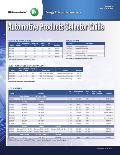
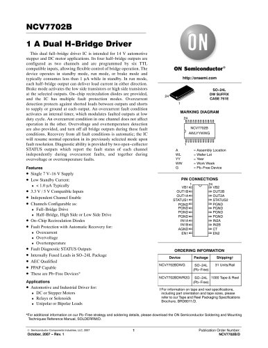
1 A Dual H-Bridge Driver
This dual full-bridge driver IC is intended for 14 V automotive
stepper and DC motor applications. Its four half-bridge outputs are
configured as two channels and are programmed by six TTL
compatible inputs, allowing flexible control of bridge operation. The
device operates in standby mode, run mode, or brake mode and
typically consumes less than 1 A while in standby. In run mode,
each half-bridge output can deliver load current in either direction.
Brake mode activates the low side transistors or high side transistors
at the selected outputs. On-chip recirculation diodes are provided,
and the IC has multiple fault protection modes. Overcurrent
detection protects against shorted loads between outputs and shorts
to supply or ground at each output. An overcurrent fault condition
activates an internal timer, which modulates faulted outputs at low
duty cycle. An overcurrent condition in one channel does not affect
operation in the other. Overvoltage and overtemperature detection
are also provided, and turn off all bridge outputs during these fault
conditions. Recovery from all fault conditions is automatic; the IC
will resume normal operation in its previously selected mode upon
fault resolution. Diagnostic ability is provided by two open-collector
STATUS outputs which report the fault status of each channel
independently during overcurrent faults, and together during
overvoltage or overtemperature faults.
Features
•Single 7 V-16 V Supply
•Low Standby Current:
< 1.0 A Typically
•3.3 V / 5 V Compatible Inputs
•Independent Channel Enable
•Channels Configurable as:
Full-Bridge Drive
Half-Bridge, High Side or Low Side Drive
•On-Chip Recirculation Diodes
•Fault Protection with Automatic Recovery for:
Overcurrent
Overvoltage
Overtemperature
•Fault Diagnostic STATUS Outputs
•Internally Fused Leads in SO–24L Package
•AEC Qualified
•PPAP Capable
•These are Pb-Free Devices*
Applications
•Automotive and Industrial Driver for:
DC or Stepper Motors
Relays or Solenoids
Unipolar or Bipolar Loads
*For additional information on our Pb-Free strategy and soldering details, please download the ON Semiconductor Soldering and Mounting
Techniques Reference Manual, SOLDERRM/D.
Device Package Shipping†
ORDERING INFORMATION
MARKING DIAGRAM
SO-24L
DW SUFFIX
CASE 751E
1
24
PIN CONNECTIONS
PGND PGND
PGND PGND
PGND PGND
PGND PGND
STATUS1 STATUS2
OUT1A OUT2A
OUT1B OUT2B
VB1 VB2
IN1A IN2A
IN1B IN2B
1 24
EN1 EN2
AGND CT
A = Assembly Location
WL = Wafer Lot
YY = Year
WW = Work Week
G = Pb-Free Device
1
NCV7702B
AWLYYWWG
24
http://onsemi.com
†For information on tape and reel specifications,
including part orientation and tape sizes, please
refer to our Tape and Reel Packaging Specifications
Brochure, BRD8011/D.
NCV7702BDWG SO-24L
(Pb-Free)
31 Units/Rail
NCV7702BDWR2G SO-24L
(Pb-Free)
1000 Tape & Reel