عضویت
عضویت  ورود اعضا
 راهنمای خرید


TR-42 Temperature Protection0 pages

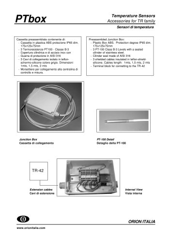
TR-42
Temperature
Monitoring & Protection
Dry type Power Transformer
Temperature Monitoring
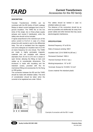
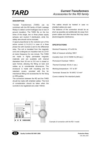
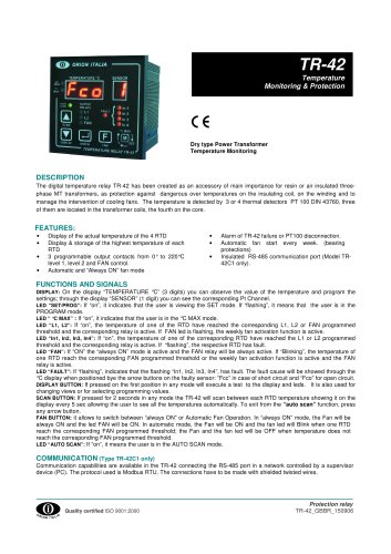
DESCRIPTION
The digital temperature relay TR-42 has been created as an accessory of main importance for resin or air insulated threephase MT transformers, as protection against dangerous over temperatures on the insulating coil, on the winding and to
manage the intervention of cooling fans. The temperature is detected by 3 or 4 thermal detectors PT 100 DIN 43760, three
of them are located in the transformer coils, the fourth on the core.
FEATURES:
•
•
•
•
Display of the actual temperature of the 4 RTD
Display & storage of the highest temperature of each
RTD
3 programmable output contacts from 0° to 220°C
level 1, level 2 and FAN control.
Automatic and “Always ON” fan mode
•
•
•
Alarm of TR-42 failure or PT100 disconnection.
Automatic fan start every week. (bearing
protections)
Insulated RS-485 communication port (Model TR42C1 only).
FUNCTIONS AND SIGNALS
DISPLAY: On the display “TEMPERATURE °C” (3 digits) you can observe the value of the temperature and program the
settings; through the display “SENSOR” (1 digit) you can see the corresponding Pt Channel.
LED “SET/PROG”: If “on”, it indicates that the user is viewing the SET mode. If “flashing”, it means that the user is in the
PROGRAM mode.
LED “ °C MAX” : If “on”, it indicates that the user is in the °C MAX mode.
LED “L1, L2”: If “on”, the temperature of one of the RTD have reached the corresponding L1, L2 or FAN programmed
threshold and the corresponding relay is active. If FAN led is flashing, the weekly fan activation function is active.
LED “In1, In2, In3, In4”: If “on”, the temperature of one of the corresponding RTD have reached the L1 or L2 programmed
threshold and the corresponding relay is active. If “flashing”, the respective RTD has fault.
LED “FAN”: If “ON” the “always ON” mode is active and the FAN relay will be always active. If “Blinking”, the temperature of
one RTD reach the corresponding FAN programmed threshold or the weekly fan activation function is active and the FAN
relay is active.
LED “FAULT”: If “flashing”, indicates that the flashing “In1, In2, In3, In4”, has fault. The fault cause will be showed through the
°C display when positioned bye the arrow buttons on the faulty sensor: ”Fcc” in case of short circuit and “Fco” for open circuit.
DISPLAY BUTTON: If pressed on the first position in any mode will execute a test to the display and leds. It is also used for
changing views or for selecting programming values.
SCAN BUTTON: If pressed for 2 seconds in any mode the TR-42 will scan between each RTD temperature showing it on the
display every 5 sec allowing the user to see all the temperatures automatically. To exit from the “auto scan” function, press
any arrow button.
FAN BUTTON: it allows to switch between “always ON” or Automatic Fan Operation. In “always ON” mode, the Fan will be
always ON and the led FAN will be ON. In automatic mode, the Fan will be ON and the fan led will Blink when one RTD
reach the corresponding FAN programmed threshold; the Fan and the fan led will be OFF when temperature does not
reach the corresponding FAN programmed threshold.
LED “AUTO SCAN”: If “on”, it means the user is in the AUTO SCAN mode.
COMMUNICATION (Type TR-42C1 only)
Communication capabilities are available in the TR-42 connecting the RS-485 port in a network controlled by a supervisor
device (PC). The protocol used is Modbus RTU. The connections have to be made with shielded twisted wires.
.
Quality certified ISO 9001:2000
Protection relay
TR-42_GBBR_150906