عضویت
عضویت  ورود اعضا
 راهنمای خرید


DM-1520 pages

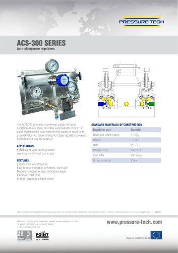
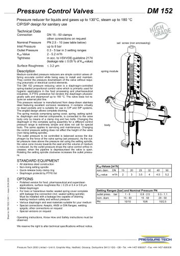
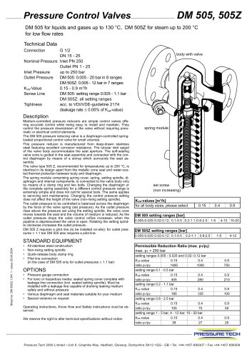
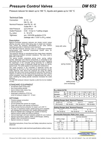
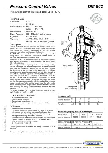
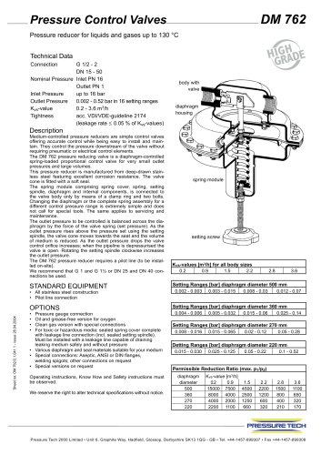
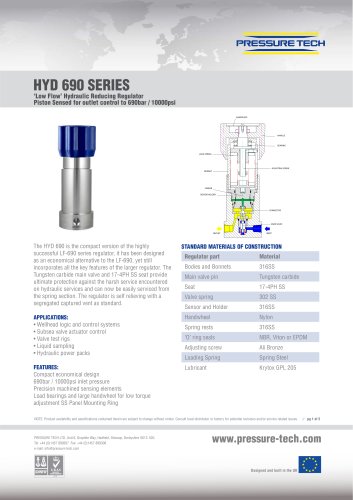
Pressure Control Valves.
nnnnDM 152
nnnnPressure reducer for liquids and gases up to 130°C, steam up to 180 °C
nnnnCIP/SIP design for sanitary use
nnnnDN 15 - 50 clamps
nnnnother connections on request
nnnnPN 2.5-10 (see table below)
nnnnup to 8 bar
nnnn0.3 - 5 bar in 3 setting ranges
nnnn2 - 5.2 m3/h
nnnnin acc. to VDI/VDE-guideline 2174
nnnn(leakage rate < 0.05 % of Kvs-value)
nnnn< 3.2 urn
nnnnTechnical Data
nnnnConnection
nnnnNominal Pressure
nnnnInlet Pressure
nnnnOutlet Pressure
nnnnKvs-Value
nnnnTightness
nnnnSurface Roughness
nnnnDescription
nnnnMedium-controlled pressure reducers are simple control valves of-
nnnnfering accurate control while being easy to install and maintain.
nnnnThey control the pressure downstream of the valve without requi-
nnnnring pneumatic or electrical control elements.
nnnnThe DM 152 pressure reducing valve is a diaphragm-controlled
nnnnspring-loaded proportional control valve which is primarily used for
nnnnhygienic applications in the food processing and pharmaceutical
nnnnindustries. A PTFE protective foil renders the diaphragm physiolo-
nnnngically safe and steamproof up to 180 °C. The valve does not re-
nnnnquire an external pilot line.
nnnnThis pressure reducer is manufactured from deep-drawn stainless
nnnnsteel featuring excellent corrosion resistance. It contains virtually
nnnnno dead pockets and is suitable for use in CIP and SIP systems.
nnnnThe angled design allows complete draining.
nnnnThe spring module comprising spring cover, spring, setting spind-
nnnnle, diaphragm and internal components, is connected to the valve
nnnnbody only by means of a clamp ring and two bolts. Changing the
nnnndiaphragm or the complete spring assembly for a different control
nnnnpressure range is extremely simple and does not call for special
nnnntools. The same applies to servicing and maintenance. Changing
nnnnthe control pressure setting does not affect the height of the valve
nnnn(non-rising setting spindle).
nnnnThe outlet pressure to be controlled is balanced across the dia-
nnnnphragm by the force of the valve spring (set pressure). As the out-
nnnnlet pressure rises above the pressure set using the setting spindle,
nnnnthe valve cone moves towards the seat and the volume of medium
nnnnis reduced. As the outlet pressure drops the valve control orifice in-
nnnncreases; when the pipeline is depressurised the valve is open.
nnnnRotating the setting spindle clockwise increases the outlet pressu-
nnnnre.
nnnnSTANDARD EQUIPMENT
nnnn• All stainless steel construction
nnnn• Non-rising setting spindle
nnnn• Quick-release body clamp ring
nnnn• Diaphragm protectd by PTFE foil
nnnnOPTIONS
nnnn• Polished version for food, pharmaceutical and superclean
nnnnapplications, surface roughness Ra < 0.25 or 0.4 or 0.8 urn
nnnn• Metal diaphragm
nnnn• For toxic or hazardous media: sealed spring cover complete
nnnnwith leakage line connection (incl. sealed setting spindle).
nnnnMust be installed with a leakage line capable of draining
nnnnleaking medium safely and without pressure
nnnn• Various diaphragm and seal materials suitable for your medium
nnnn• Special connections: Aseptic, ANSI or DIN flanges, welding
nnnnspigots; other connections on request
nnnn• Special versions on request
nnnnOperating instructions, Know How and Safety instructions must be
nnnnobserved.
nnnnset screw (non encreasing)
nnnnspring module
nnnnbody
nnnnKVs-Values [m3/h | ||||||
nom. diam. DN | 15 | 20 | 25 | 32 | 40 | 50 |
Kvs-value m3/h | 2 | 3 | 3.5 | 4 | 4.5 | 5.2 |
Setting Ranges [bar] and Nominal Pressure PN | |||
outlet press, bar | 1 - 5 | 0.8-2.5 | 0.3-1.1 |
nom. diam. | 15-50 | 15-50 | 20-50 |
PN | 10/10 | 10/6 | 10/2.5 |
We reserve the right to alter technical specifications without notice.
nnnnPRESSURETECH
nnnnPressure Tech 2000 Limited • Unit 6, Graphite Way, Hadfield, Glossop, Derbyshire SK13 1QG - GB • Tel. +44-1457-899307 • Fax +44-1457-899308
"