عضویت
عضویت  ورود اعضا
 راهنمای خرید


KERAPLAST ceramic heater bands for plastification cylinders0 pages
KERAPLAST
Application: Heating of Plastification Cylinders
KERAPLAST
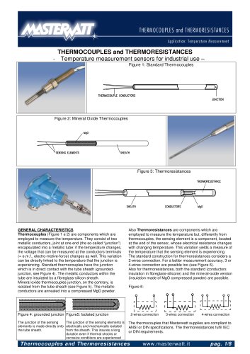
- High Power Heater Bands for Plastification Cylinders Figure 1
GENERAL CHARACTERISTICS
The continuous technological development in the moulding of
plastic materials demands to all the machine components
high performances and reliability. The long experience in this
field and a specific technical solution allowed us to produce a
family of heaters which fulfils these tight requirements. They
have imposed throughout the market and have made us
leaders in this field.
KERAPLAST heaters belong to the new generation of
electrical heaters for the plastic industry and have become
components of primary importance for the smooth operation
of the moulding machine. The selection of the best materials,
allows to reach very high heating power values and presents
several advantages. In particular it is worth to mention:
§
§
§
§
§
§
§
Long Operational Life
Energy saving
Fast heat conduction
Uniform heat distribution
High electrical insulation
Easy installation
Great mechanical resistance to shocks and to tearing
applied to the cables
§ Tight manufacturing tolerances
executed with automatic tools which insure long duration.
The spiral is uniformly distributed within the circuit which
is realised by a mosaic of ceramic blocks. This solution
guarantees a perfect distribution of the heat
2. ELECTRICAL INSULATION made of high purity ceramic
KER 221 DIN 40685 which presents a high resistance to
thermal shocks and a high dielectrical rigidity. The
peculiar internal structure of the ceramic insures a rapid
and uniform transmission of the heat. Thanks to the high
temperatures which are reached and to the particular
shape of the mosaic, the heat is transmitted both by
conduction and radiation.
3. CERAMIC TERMINAL BOARD connecting the power
supply cables to the internal electrical circuit. A special
metallic cover protects the ceramic board from shocks
and tearings applied to the cables
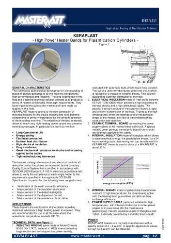
4. INTERNAL INSULATION made of fibreglass which allows
to save electrical energy: the graph below shows, for a 24
hours working cycle, that saving that can be obtained if a
KERAPLAST heater is used in place of a MIKAPLAST is
about 20 %.
24
test time (h)
21
The heaters undergo dimensional and electrical controls all
along the production phase, as requested by the company
Quality Control System that is certified in accordance with
ISO 9001:2000 Standard. A 100 % electrical acceptance test
allows to verify the compliance of each single heater to the
requirements specified in the applicable CEI/EN/UL
Specification. In particular, the following tests are performed:
18
15
Mikaplast
12
Keraplast
9
6
3
0
0
1
2
3
4
5
6
7
energy consumption (kWh)
§
§
§
§
§
Verification of the earth connector efficiency
Measurement of the Insulation resistance
Measurement of the dielectrical rigidity
Measurement of the dispersion current
Measurement of the resistance ohmic value
APPLICATIONS
These heaters are employed in all the plastic moulding
machines whenever a high heating power is required. They
are recommended for use in all the case where the
operational temperature exceeds 280 °C.
KERAPLAST
POWER
KERAPLAST heaters are normally manufactured with a
2
specify power of 4 ÷ 6 W/cm . In specific applications values
as high as 8 W/cm² can be obtained.
www.masterwatt.it
pag. 1/2
Issue 2004
TECHNICAL DATA (see Figure 1)
1. RESISTIVE WINDING spiral made of Nickel/Chrome
80/20 DIN 17470, material n° 4869, characterised by
large section and consequent low power density,
5. INTERNAL SHEATH made of galvanically treated steel
resistant to high temperatures. Its compressing action
onto the heating band guarantees an optimum heat
exchange efficiency
6. POWER SUPPLY CABLE (optional) suitable for high
temperatures, with internal conductors in nickel-plated
copper or in pure nickel (for the most severe
applications). Internal insulation made of fibreglass and
Teflon. Externally protected by a metallic braid sheath.