عضویت
عضویت  ورود اعضا
 راهنمای خرید


Cartridge Filter0 pages

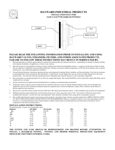
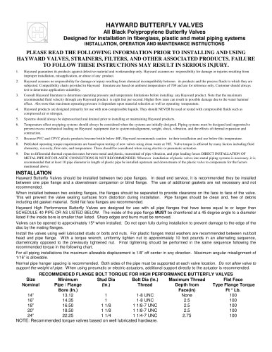
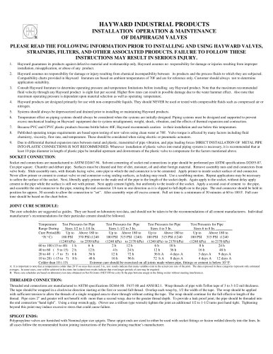
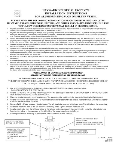
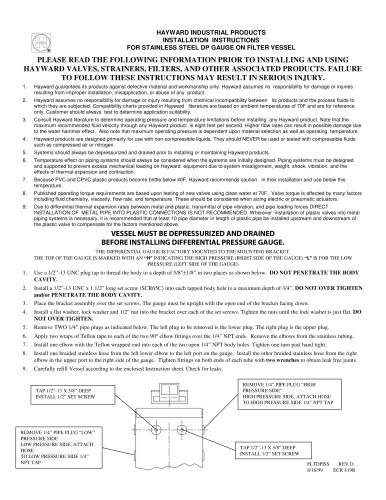
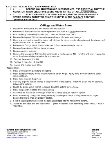
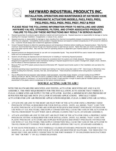
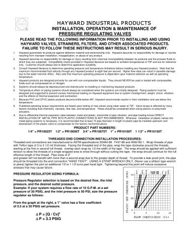
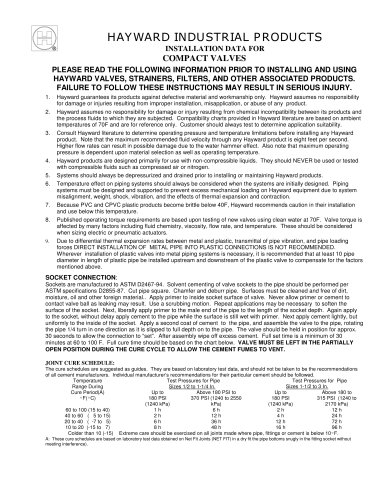
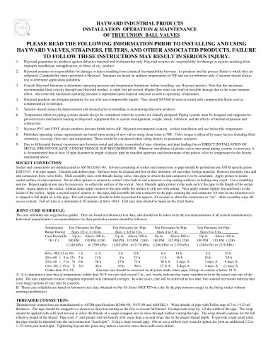
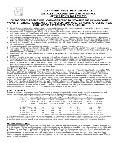
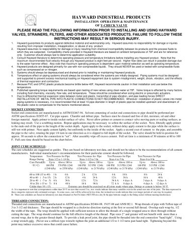
INSTALLATION, OPERATION AND MAINTENANCE PLEASE READ THE FOLLOWING INFORMATION PRIOR TO INSTALLING AND USING HAYWARD VALVES, STRAINERS, FILTERS, AND OTHER ASSOCIATED PRODUCTS. FAILURE TO FOLLOW THESE INSTRUCTIONS MAY RESULT IN SERIOUS INJURY.
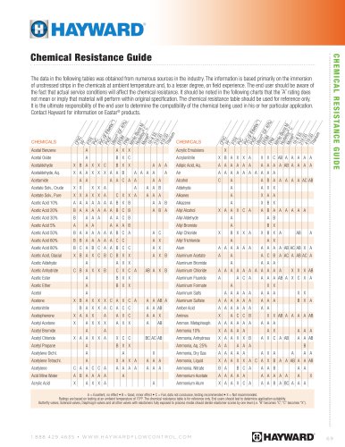
1. Hayward guarantees its products against defective material and workmanship only. Hayward assumes no responsibility for damage or injuries resulting from improper installation, misapplication, or abuse of any product. 2. Hayward assumes no responsibility for damage or injury resulting from chemical incompatibility between its products and the process fluids to which they are subjected. Compatibility charts provided in Hayward literature are based on ambient temperatures of 70F and are for reference only. Customer should always test to determine application suitability. 3. Consult Hayward literature to determine operating pressure and temperature limitations before installing any Hayward product. Note that the maximum recommended fluid velocity through any Hayward product is eight feet per second. Higher flow rates can result in possible damage due to the water hammer effect. Also note that maximum operating pressure is dependent upon material selection as well as operating temperature. 4. Hayward products are designed primarily for use with non-compressible liquids. They should NEVER be used or tested with compressible fluids such as compressed air or nitrogen. 5. Systems should always be depressurized and drained prior to installing or maintaining Hayward products. 6. Temperature effect on piping systems should always be considered when the systems are initially designed. Piping systems must be designed and supported to prevent excess mechanical loading on Hayward equipment due to system misalignment, weight, shock, vibration, and the effects of thermal expansion and contraction. 7. Because PVC and CPVC plastic products become brittle below 40F, Hayward recommends caution in their installation and use below this temperature. 8. Published operating torque requirements are based upon testing of new valves using clean water at 70F. Valve torque is affected by many factors including fluid chemistry, viscosity, flow rate, and temperature. These should be considered when sizing electric or pneumatic actuators. 9. Due to differential thermal expansion rates between metal and plastic, transmittal of pipe vibration, and pipe loading forces DIRECT INSTALLATION OF METAL PIPE INTO PLASTIC CONNECTIONS IS NOT RECOMMENDED. Wherever installation of plastic valves into metal piping systems is necessary, it is recommended that at least 10 pipe diameter in length of plastic pipe be installed upstream and downstream of the plastic valve to compensate for the factors mentioned above. >
nnINSTALLATION:
nnINSPECTION
Upon receipt of the filter vessel, inspect it for damage that might have occurred during transit. Report any damage to the carrier immediately. >
nnLOCATION AND SUPPORT
The Hayward filter vessel should be installed not less than 24 down stream of a Hayward strainer. The filter vessel must be bolted to the floor to insure proper piping installation. A integral flange on the base of the g filter vessel will accept 3/4Ԕ studs. >
nnPIPING INSTALLATION WARNING: METAL PIPING SHOULD INCLUDE A MINIMUM OF 20Ғ OF PLASTIC PIPE UPSTREAM AND DOWNSTREAM OF THE FILTER VESSEL.
DO NOT FORGET THE O-RING. For installation in metal piping systems it is recommended that the Hayward flanged version CFLT4202F or CFLT4201F be installed. Plastic piping is still required. From the Hayward strainer, a 2 line is required to the inlet of the filter vessel. Connect 2Ԕ line to a valve and then to the upper 2 NPTF (inlet) of the filter vessel. A 2Ԕ line must be piped from the filter vessel 2 NPTF bottom port (outlet) to a determined suction source (system pump suction). A 2Ԕ valve such as a Hayward Diaphragm or Butterfly valve is required on this outlet line. It is recommended that a 2 drain valve be installed on the unused bottom 2Ԕ NPT port The vent fitting must be installed on the top of the unit. A 3/8 ID tube should be attached over the barb and secured with a hose clamp on the vent fitting. This hose will be used to direct the flow from the vent fitting. The top of the vent fitting is normally plugged. This plug can be removed and replaced with a pressure gauge that measures inlet pressure to the bag filter. It is recommended that a gauge guard be installed between the filter vent and the gauge. >
nnTHREADED CONNECTION:
Threaded end connections are manufactured to ASTM specifications D2464-88. F437-88 and ANSI B2.1. Wrap threads of pipe with Teflon tape of 3 to 3-1/2 mil thickness. The tape should be wrapped in a clockwise direction starting at the first or second full thread. Overlap each wrap by, 1/2 the width of the tape. The wrap should be applied with sufficient tension to allow the threads of a single wrapped area to show through without cutting the tape. The wrap should continue for the full effective length of the thread. Pipe sizes 2Ԕ and greater will not benefit with more than a second wrap, due to the greater thread depth. To provide a leak proof joint, the pipe should be threaded into the end connection hand tightӔ. Using a strap wrench only . (Never use a stillson type wrench) tighten the joint an additional 1/2 to 1-1/2 turns past hand tight. Tightening beyond this point may induce excessive stress that could cause failure. >
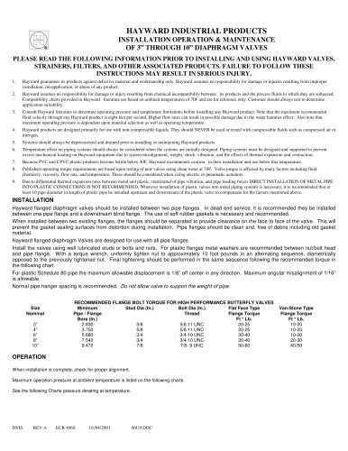
nnFLANGED CONNECTION:
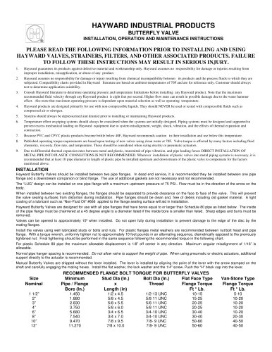
RECOMMENDED FLANGE BOLT TORQUE Flange bolts should be tight enough to slightly compress the gasket and make a good seal, without distorting or putting excessive stress on the flanges. Suitable washers should be used between the bolt head and flange and the nut and flange. Bolts should be tightened in alternating sequence. >
nnUSE WELL LUBRICATED METAL BOLTS AND NUTS. USE SOFT RUBBER GASKETS
FLANGE SIZE BOLT DIAMETER. TORQUE FT. LBS. 2 5/8 15-25 >
"