عضویت
عضویت  ورود اعضا
 راهنمای خرید


PRD/PRDW Series0 pages
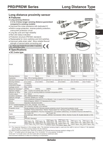
PRD/PRDW Series
Long Distance Type
Long distance proximity sensor
(A)
Photo
electric
sensorr
Features
Line-up
● Long sensing distance
(1.5 to 2 times longer sensing distance guaranteed
compared to existing models)
● Improved the noise resistance with dedicated IC
● Built-in surge protection, reverse polarity protection,
overcurrent protection circuit
● Long life cycle and high reliability
● Red LED status indication
● Protection structure IP67(IEC standard)
● Replaceable for micro switches and limit switches
● Improved cable strain relief : More reliable flexural
strength of sensor/cable connecting part
(B)
Fiber
optic
sensor
(C)
Door/Area
sensor
(D)
Proximity
sensor
(E)
Pressure
sensor
(F)
Rotary
encoder
Please read “Caution for your safety” in operation
manual before using.
(G)
Connector/
Socket
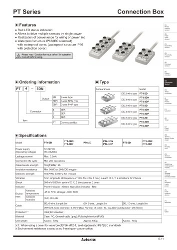
Specifications
● DC 2-wire type
Model
PRDT12-4□O
PRDT12-4□C
PRDT12-4□O-V
PRDT12-4□C-V
PRDLT12-4□O
PRDLT12-4□C
PRDLT12-4□O-V
PRDLT12-4□C-V
PRDWT12-4□O
PRDWT12-4□C
PRDWT12-4□O-I
PRDWT12-4□C-I
PRDWT12-4□O-IV
PRDWT12-4□C-IV
PRDT12-8□O
PRDT12-8□C
PRDT12-8□O-V
PRDT12-8□C-V
PRDLT12-8□O
PRDLT12-8□C
PRDLT12-8□O-V
PRDLT12-8□C-V
PRDWT12-8□O
PRDWT12-8□C
PRDWT12-8□O-I
PRDWT12-8□C-I
PRDWT12-8□O-IV
PRDWT12-8□C-IV
PRDT18-7□O
PRDT18-7□C
PRDT18-7□O-V
PRDT18-7□C-V
PRDLT18-7□O
PRDLT18-7□C
PRDLT18-7□O-V
PRDLT18-7□C-V
PRDWT18-7□O
PRDWT18-7□C
PRDWT18-7□O-I
PRDWT18-7□C-I
PRDWT18-7□O-IV
PRDWT18-7□C-IV
PRDWLT18-7□O-IV
PRDWLT18-7□C-IV
7mm
PRDT18-14□O
PRDT18-14□C
PRDT18-14□O-V
PRDT18-14□C-V
PRDLT18-14□O
PRDLT18-14□C
PRDLT18-14□O-V
PRDLT18-14□C-V
PRDWT18-14□O
PRDWT18-14□C
PRDWT18-14□O-I
PRDWT18-14□C-I
PRDWT18-14□O-IV
PRDWT18-14□C-IV
PRDWLT18-14□O-IV
PRDWLT18-14□C-IV
14mm
PRDT30-15□O
PRDT30-15□C
PRDT30-15□O-V
PRDT30-15□C-V
PRDLT30-15□O
PRDLT30-15□C
PRDLT30-15□O-V
PRDLT30-15□C-V
PRDWT30-15□O
PRDWT30-15□C
PRDWT30-15□O-I
PRDWT30-15□C-I
PRDWT30-15□O-IV
PRDWT30-15□C-IV
PRDT30-25□O
PRDT30-25□C
PRDT30-25□O-V
PRDT30-25□C-V
PRDLT30-25□O
PRDLT30-25□C
PRDLT30-25□O-V
PRDLT30-25□C-V
PRDWT30-25□O
PRDWT30-25□C
PRDWT30-25□O-I
PRDWT30-25□C-I
PRDWT30-25□O-IV
PRDWT30-25□C-IV
Sensing distance
4mm
8mm
15mm
25mm
Hysteresis
Max. 10% of sensing distance
Standard sensing target 12×12×1mm(Iron) 25×25×1mm (Iron) 20×20×1mm (Iron) 40×40×1mm (Iron) 45×45×1mm (Iron) 75×75×1mm (Iron)
Sensing distance
0 to 2.8mm
0 to 5.6mm
0 to 4.9mm
0 to 9.8mm
0 to 10.5mm
0 to 17.5mm
12-24VDC
Power supply
(Operating voltage)
(10-30VDC)
Leakage current
Max. 0.6mA
※1
Response frequency
450HZ
400Hz
250Hz
200Hz
100Hz
Residual voltage※2
Max. 3.5V(for non-polarity type, max. 5V)
Affection by Temp.
Max. ±10% for sensing distance at ambient temperature 20℃
Control output
2 to 100mA
Insulation resistance
Min. 50MΩ(at 500VDC megger)
Dielectric strength
1500VAC 50/60Hz for 1minute
Vibration
1mm amplitude at frequency of 10 to 55Hz(for 1 min.) in each of X, Y, Z directions for 2 hours
Shock
500m/s²(approx. 50G) X, Y, Z directions for 3 times
Indicator
Operation indicator(red LED)
Environ‑ Ambient temperature -25 to 70℃, Storage: -30 to 80℃
ment
Ambient humidity 35 to 95%RH, Storage: 35 to 95%RH
Protection circuit
Surge protection circuit, Reverse polarity protection circuit, Overcurrent protection circuit
Case/Nut: Nickel plated Brass, Washer: Nickel plated Iron, Sensing surface: Heat-resistant ABS,
Material
Standard cable(Black): Polyvinyl chloride(PVC), Oil resistant cable(Gray): Oil resistant Polyvinyl chloride(PVC)
ø4, 2-wire, 2m
ø5, 2-wire, 2m
Cable
(For cable type, 300mm, M12 connector), (AWG22, Core diameter: 0.08mm, Number of cores: 60, Insulator diameter: ø1.25)
Approval
Protection
IP67(IEC Standard)
PRDT: Approx. 115g PRDT: Approx. 110g
PRDT: Approx. 175g
PRDT: Approx. 180g
PRDT: Approx. 74g PRDT: Approx. 72g
PRDLT: Approx. 145g PRDLT: Approx. 140g
PRDLT: Approx. 215g PRDLT: Approx. 220g
PRDLT: Approx. 94g PRDLT: Approx. 92g
Unit weight
PRDWT: Approx. 80g PRDWT: Approx. 75g
PRDWT: Approx. 44g PRDWT: Approx. 42g
PRDWLT: Approx. 42g PRDWLT: Approx. 105g PRDWT: Approx. 140g PRDWT: Approx. 145g
※1: The response frequency is the average value. The standard sensing target is used and the width is set as 2 times of the standard
sensing target, 1/2 of the sensing distance for the distance.
※2: Before using non-polarity type, check the condition of connected device because residual voltage is 5V.
※The '□' of model name is for power type. 'D' is 12-24VDC, 'X' is non-polarity 12-24VDC.
※The last 'V' of model name is for the model with oil-resistance reinforced cable.
※Environment resistance is rated at no freezing or condensation.
D-11
(H)
Temp.
controller
(I)
SSR/
Power
controller
(J)
Counter
(K)
Timer
(L)
Panel
meter
(M)
Tacho/
Speed/ Pulse
meter
(N)
Display
unit
(O)
Sensor
controller
(P)
Switching
mode power
supply
(Q)
Stepper
motor&
Driver&Controller
(R)
Graphic/
Logic
panel
(S)
Field
network
device
(T)
Software
(U)
Other