عضویت
عضویت  ورود اعضا
 راهنمای خرید


Model M1714B Maxiflex MP Module0 pages
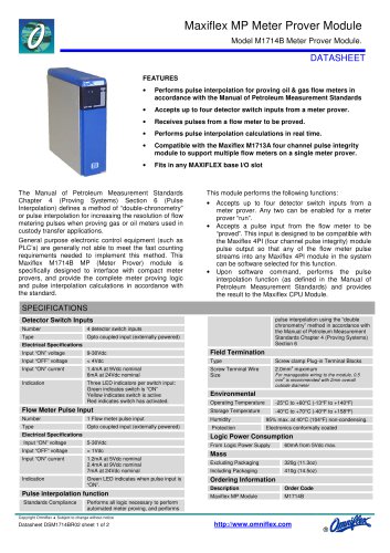
Maxiflex MP Meter Prover Module
Model M1714B Meter Prover Module.
DATASHEET
FEATURES
•
Performs pulse interpolation for proving oil & gas flow meters in
accordance with the Manual of Petroleum Measurement Standards
•
Accepts up to four detector switch inputs from a meter prover.
•
Receives pulses from a flow meter to be proved.
•
Performs pulse interpolation calculations in real time.
•
Compatible with the Maxiflex M1713A four channel pulse integrity
module to support multiple flow meters on a single meter prover.
•
Fits in any MAXIFLEX base I/O slot
The Manual of Petroleum Measurement Standards
Chapter 4 (Proving Systems) Section 6 (Pulse
Interpolation) defines a method of “double-chronometry”
or pulse interpolation for increasing the resolution of flow
metering pulses when proving gas or oil meters used in
custody transfer applications.
General purpose electronic control equipment (such as
PLC’s) are generally not able to meet the fast counting
requirements needed to implement this method. This
Maxiflex M1714B MP (Meter Prover) module is
specifically designed to interface with compact meter
provers, and provide the complete meter proving logic
and pulse interpolation calculations in accordance with
the standard.
This module performs the following functions:
•
•
•
Accepts up to four detector switch inputs from a
meter prover. Any two can be enabled for a meter
prover “run”.
Accepts a pulse input from the flow meter to be
“proved”. This input is designed to be compatible with
the Maxiflex 4PI (four channel pulse integrity) module
pulse output so that any of the flow meter pulse
streams into any Maxiflex 4PI module in the system
can be software selected for this function.
Upon software command, performs the pulse
interpolation function (as defined in the Manual of
Petroleum Measurement Standards) and provides
the result to the Maxiflex CPU Module.
SPECIFICATIONS
pulse interpolation using the “double
chronometry” method in accordance with
the Manual of Petroleum Measurement
Standards Chapter 4 (Proving Systems)
Section 6
Detector Switch Inputs
Number
4 detector switch inputs
Type
Opto coupled input (externally powered)
Electrical Specifications
Input “ON” voltage
9-30Vdc
Field Termination
Input “OFF” voltage
< 4Vdc
Type
Screw clamp Plug-in Terminal Blocks
Input “ON” current
1.4mA at 9Vdc nominal
6mA at 24Vdc nominal
Screw Terminal Wire
Size
2.0mm2 maximum
Indication
Three LED indicators per switch input:
Green indicates switch is “ON”
Yellow indicates switch is active
Red indicates switch has activated.
Environmental
For manageable wiring to the module, 0.5
mm2 is recommended with 2mm overall
outside diameter
Operating Temperature
-25°C to +60°C (-13°F to +140°F)
Flow Meter Pulse Input
Storage Temperature
Number
1 Flow meter pulse input
Humidity
95% max. at 40°C (104°F) non-condensing.
Type
Opto coupled input (externally powered)
Protection
Electronics conformally coated
Electrical Specifications
Logic Power Consumption
Input “ON” voltage
5-30Vdc
Input “OFF” voltage
< 1Vdc
Input “ON” current
1.2mA at 5Vdc nominal
2.4mA at 9Vdc nominal
7mA at 24Vdc nominal
Indication
Green LED indicates when pulse input is
“ON”.
Pulse interpolation function
Standards Compliance
-40°C to +70°C (-40°F to +158°F)
From Logic Power Supply
60mA from 5Vdc max.
Mass
Excluding Packaging
320g (11.3oz)
Including Packaging
410g (14.5oz)
Ordering Information
Description
Order Code
Maxiflex MP Module
M1714B
Performs all logic necessary to perform
automated meter proving, and performs
Copyright Omniflex ♦ Subject to change without notice
Datasheet DSM1714BR02 sheet 1 of 2
http://www.omniflex.com
®
"